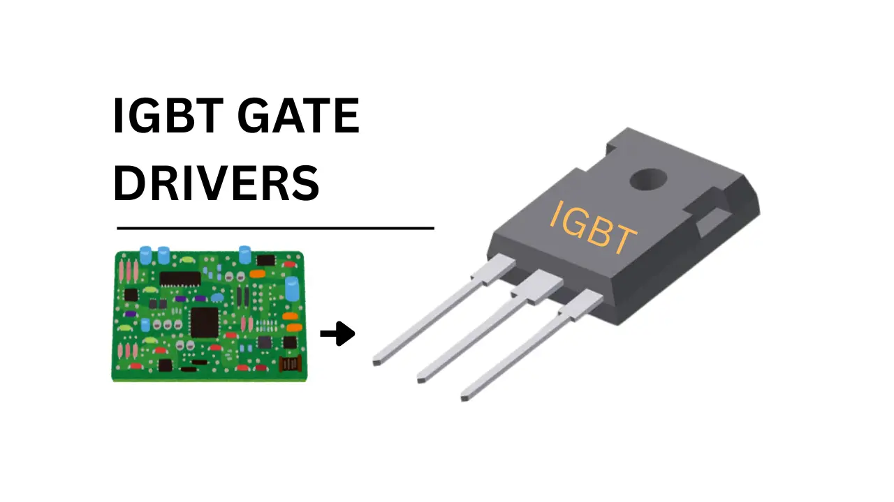
The IGBT are most common electronic component present in the power electronics like Induction cooktop, Motor driver, Power inverter and other Household appliances. The IGBT gate drivers are specially designed circuit to turn On and OFF IGBT safely. Because the IGBT needs +15V DC to turn ON and 0V to -5/-15V for Turn off safely.
What IGBT Drivers Doing
The IGBT driver circuits providing the required voltage and current for the Gate Pin of the IGBT to turn ON and OFF. This voltage is can not directly produced by the small micro controller chip, so additional power is injecting using the gate driver boars.
The gate drivers also providing the fast switching function (fast turn On and Off) which will minimizing the power loss and improving the efficiency of the external signal generating circuit.
In driver circuit optocouplers or mini transformers are using to control the gate pin of the IGBT, which will giving the proper isolation of the connected circuit and improving the safety of other electronic components.
Additional Protection Features of IGBT Drivers
- Under voltage lockout (UVLO)
- Desaturation detection, which will detects the short circuits.
- Soft shutdown is used to avoid voltage overshoot.
- Miller clamp is prevents the false turn-on.
Basic Block Diagram of IGBT Drivers
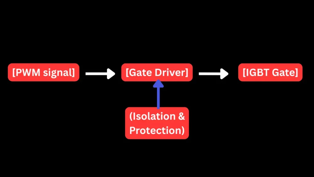
The block diagram of an IGBT gate driver is consists of three main sections which are input interface, isolation stage and the gate driving stage. The input section receives the low voltage control signal from a PWM signal of a microcontroller or other PWM control IC.
This signal is then passed through an isolation barrier using optocouplers or transformers. This isolation is critical because it protects the low voltage control circuits side from the very high voltages from the IGBT section.
After isolation, the signal is enters the gate driving stage and which is amplifies it to the required voltage and current levels needed to switch the IGBT efficiently. This stage includes circuits to supply a positive gate voltage (e.g., +15V) for turn on and a zero or negative voltage (e.g., 0V or -15V) for turn off gate pin.
Additional the protection features are also integrated in may circuits, such as under voltage lockout (UVLO), desaturation detection (to monitor short circuits) and a soft shutdown (to avoid damaging voltage spikes). Overall, the gate driver ensures the IGBT operates safely and efficiently in high-power switching applications.
IGBT Gate Drive Signal Levels
| Mode | Gate Voltage | Purpose |
|---|---|---|
| ON | +15V | Fully turn ON IGBT |
| OFF | 0V or -5V to -15V | Fully turns off IGBT |
| Fault | Soft shutdown or -15V | Safe turn off voltage |