The TL494 IC based circuit can able to generate the PWM signals based on the jumper connection. If you are changing the jumper connection you can select different frequency (50Hz to 300Khz) in the output. In this article, sharing the circuit diagram, components list, explanations and Schematic files to download.
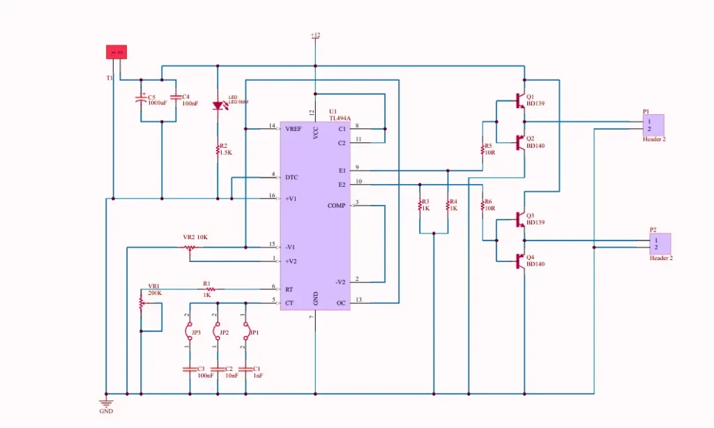
494 IC PWM Generator Circuit Diagram
This circuit consist of main three parts, which are the Totem pole drivers, PWM IC circuit and Jumpers to selecting the output frequency.
Components Required
| Name | Designator | Description |
|---|---|---|
| 1nF | C1 | Bipolar Capacitor |
| 10nF | C2 | Bipolar Capacitor |
| 100nF | C3 | Bipolar Capacitor |
| 100nF | C4 | CAP Ceramic Total |
| 1000uF | C5 | Cap electrolytic radial |
| Jumper | JP1 | Jumper |
| Jumper | JP2 | Jumper |
| Jumper | JP3 | Jumper |
| LED 5MM | LED | Light Emitting Diode |
| Header 2 | P1 | Header, 2-Pin |
| Header 2 | P2 | Header, 2-Pin |
| BD139 | Q1 | Bipolar BJT Transistor |
| BD140 | Q2 | Bipolar BJT Transistor |
| BD139 | Q3 | Bipolar BJT Transistor |
| BD140 | Q4 | Bipolar BJT Transistor |
| 1K | R1 | RES Axial 0.25W |
| 1.5K | R2 | RES Axial 0.25W |
| 1K | R3 | RES Axial 0.25W |
| 1K | R4 | RES Axial 0.25W |
| 10R | R5, R6 | RES Axial 0.25W |
| KF301_Terminal | T1 | Terminal 2 Pin 250V |
| TL494A | U1 | – |
| 200K | VR1 | Variable Resistor |
| 10K | VR2 | Variable Resistor |
Circuit Explanation and Working
The TL494 IC based PWM module is used for power supply regulation and DC voltage control for motor driving. At the heart of this module is the TL494 pulse width modulation controller IC. The IC is responsible for generating precise PWM signals to drive the power transistors. The circuit includes essential components such as timing resistors and capacitors (RT and CT) which will determine the switching frequency, along with a compensation network for stability. The Voltage regulation and feedback are achieved by using the internal error amplifiers and an adjustable reference voltage provided by the TL494.
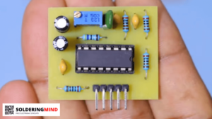
This module is designed with pair of bipolar junction transistors (BJTs) like BD139 and BD140. which functioning as a power drivers for external loads. The use of variable resistors (potentiometers) allowing to tuning parameters such as duty cycle. Filtering capacitors, including a 1000µF electrolytic capacitor and smaller decoupling capacitors, help to smoothen voltage levels and reduce noise. The presence of LED indicators, jumpers, and terminal headers makes the circuit user-friendly and easy to integrate into other systems.