In the old days, we saw many analogue PIR sensors that worked with op-amp ICs. The analogue sensors only give LOW or HIGH. This ZDP323 digital sensor uses I2C digital lines to share data and settings with the microcontroller IC. In this article, I’m sharing useful information about this digital PIR sensor.
Introduction to the ZDP323 PIR Sensor
The Zilog ZDP323 is an advanced PIR module. This is a low power PIR Motion sensor device that comes with I2C interfacing. So the sensor can easily communicate with the connected microcontroller IC. This component comes in a TO-5 metal package with 4 pins.
This digital PIR sensor can be configured through the I2C connections and we can set the sensitivity for the motion that needs to be detected. It can filter unwanted signals and trigger only when a clean detection appears. The I2C data connection activates the IC if any motion is detected based on the programming. Lest see its key features and specifications,
ZDP323 Key Features and Specifications
- Working voltage is 1.5V to 5.5V.
- Working current is relatively ultra low it is about 3uA.
- Field of view is 148°× 136°
- Operating temperature is -40℃ to 80℃
- I²C or UART interface with a triggered output mode
- Comes in TO-5 Packaging with 4 pins.
- We can program the gain, detection threshold and filter profile.
Pin Configuration and Pinout Diagram
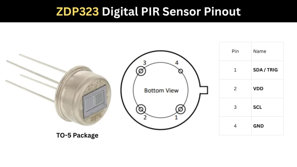
Pinout Configurations
| Pin | Name | Description |
|---|---|---|
| 1 | SDA / TRIG | SDA: I²C Serial Data line used for transferring data to and from the external I²C master. TRIG which is Motion trigger output that is driven low when motion is detected. |
| 2 | VDD | Power supply input pin. (1.5V to5.5V DC) |
| 3 | SCL | I²C Serial Clock input from the external I²C master. |
| 4 | GND | Ground connection reference for the device. |
🛒 You can purchase the ZDP323AA Digital PIR from this from Mouser Electronics.
How the ZDP323 PIR Sensor Works
This works the same way as an analogue PIR sensor, detecting the infrared signal from the human body or a hot surface. Every human body emits infrared radiation, which is captured by the two sensors built into this component. When an IR signal is detected, the baseline of the sensor is disrupted and motion is sensed.
I2C Communication Interface
The Pin number 1 and Pin number 3 is the I2C connection pins. Which are,
- SDA/TRIG – It is a serial data in and out pin. Also activated when the motion detected and act as the trigger pin.
- SCL is the third pin which act as a clock pin. It connected to The Microcontroller for getting Serial clock input.
Interfacing the ZDP323 with Arduino
A simple LED based motion detector code is given. It is for demonstrating the working of the digital PIR sensor. The ZDP323 sensor monitors heat changes and pulls its data line LOW the instant it detects human movement.
Connection Details
- VDD (Power Supply) is connect to 3.3V or 5V on the Arduino Uno.
- GND (Ground) is connect to any GND pin on the Arduino Uno.
- SCL (I²C Clock) which is connect to the pin A5 (or the dedicated SCL pin on newer Arduino boards).
- Requires an external or onboard pull-up resistor connected to VDD.
- SDA/TRIG (I²C Data / Motion Trigger) is connect to A4 (or the dedicated SDA pin) for I²C communication.
- The same pin can also be connected to Digital Pin 2 on the Arduino Uno if hardware interrupt-based motion detection is required.
- Requires a pull-up resistor to VDD for reliable I²C operation.
Programming Code
#include <Wire.h>

// Define Pins
const int motionInterruptPin = 2; // Connected to ZDP323 SDA/TRIG pin
const int ledPin = 13;            // Built-in Arduino LED

// Volatile variable to track motion events across interrupts
volatile bool motionDetected = false;

// Interrupt Service Routine (ISR)
void ICACHE_RAM_ATTR motionISR() {
  motionDetected = true;
}

void setup() {
  Serial.begin(115200);
  while (!Serial); // Wait for Serial Monitor to open

  pinMode(ledPin, OUTPUT);

  // Set up the interrupt pin with an internal pull-up resistor
  // (though external 4.7k-10k pull-ups are highly recommended on I2C lines)
  pinMode(motionInterruptPin, INPUT_PULLUP);

  // Attach interrupt to trigger on a FALLING edge (when SDA/TRIG goes low)
  attachInterrupt(digitalPinToInterrupt(motionInterruptPin), motionISR, FALLING);

  // Initialize I2C communication (if you intend to configure registers later)
  Wire.begin();

  Serial.println("ZDP323 Motion Sensor Initialized.");
  Serial.println("Waiting for stabilization (takes ~30 seconds)...");

  // Give the digital PIR sensor element time to stabilize its baseline thermal footprint
  delay(30000);
  Serial.println("Sensor Ready!");
}

void loop() {
  // Check if the ISR flagged a motion event
  if (motionDetected) {
    // Visually confirm motion
    digitalWrite(ledPin, HIGH);
    Serial.println("--> MOTION DETECTED! <--");

    // --- Optional advanced functionality ---
    // If you need to read the internal data/registers (like Peak Hold values)
    // to distinguish which sensor triggered on a shared bus, do it here:
    // readSensorData();

    // Keep the LED on for a short duration to make it visible
    delay(1000);
    digitalWrite(ledPin, LOW);

    // Clear the flag to wait for the next interrupt
    motionDetected = false;
  }
}
The Arduino catches this quick voltage drop via a hardware interrupt pin, flashes an LED, and prints an alert to the screen without needing to constantly poll the sensor.
Applications
- Motion activated lighting systems.
- Smart home automation and occupancy detection.
- Security and intrusion alarm systems.
- Battery powered IoT motion sensing devices.