The UM66 IC is a popular melody generator integrated circuit used in various simple sound producing electronic projects. Most common in hobby electronics projects and It is a small three pin IC that can produce a pleasant musical tones when it powered, so it is it a best choice for toys, doorbells and hobby circuits.
What is UM66 Melody Generator IC?
The UM66 is (also known as UM66TXX series) a CMOS melody generator IC. It contains a pre programmed ROM that stores with a melody, tone generator and control circuitry for automatic playback. When The IC is powered with a small voltage (around 1.5V–3.3V), that time it generates a musical output signal that can be amplified using a transistor to drive a speaker.
UM66 IC Pinout
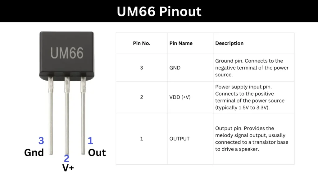
When you hold the UM66 transistor type IC with its flat surface facing you and the pins pointing downward toward the ground, then count the pins from right to left as 1, 2, and 3. In this orientation, pin 1 serves as the melody output pin, pin 2 is the positive supply pin, and pin 3 is the ground pin for the negative supply.
Features of UM66 IC
- Operates on low voltage (1.5V to 3.3V)
- Low power consumption
- Inbuilt melody ROM
- Compact TO-92 package (resembles a transistor)
- Ideal for musical projects and toys
Working Principle and Pin Connection in Melody Generator Circuit
The working principle of this UM66 IC is very simple and easy to understand. When the UM66 IC is connected with the 1.5 or 3v DC power, it automatically starts to generating a melody signal through its output pin of Pin number 1. This signal is very weak signal so it cannot directly drive a speaker.
To amplify the out put signals the output is connected to the base pin of a transistor we can use BC547 or BC548 to do this. This transistor then drives a small speaker or buzzer to hear the sound loudly by amplifying the input signal.
In this IC based melody generator circuit, the Pin 2 of the IC is connected to a 3V battery. The Pin 3 is connected to the negative terminal and the melody output is getting from the Pin 1. The Pin 1 is then connected to the base of a transistor through a small resistor and amplifying the output signal.
Applications
- Musical greeting cards
- Doorbell circuits
- Toy sound modules
- Hobby and DIY melody projects
- Alarm sound generators