This circuit is using TP4056 Li ion battery charging controll IC and additional Protection IC which is DW01A. Combination of both of the IC, we can get a efficient battery charging system. So in this article i’m sharing the Circuit diagram, connection details and features of this new Battery charging circuit.
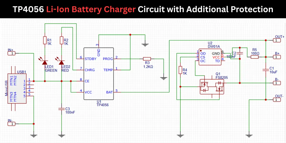
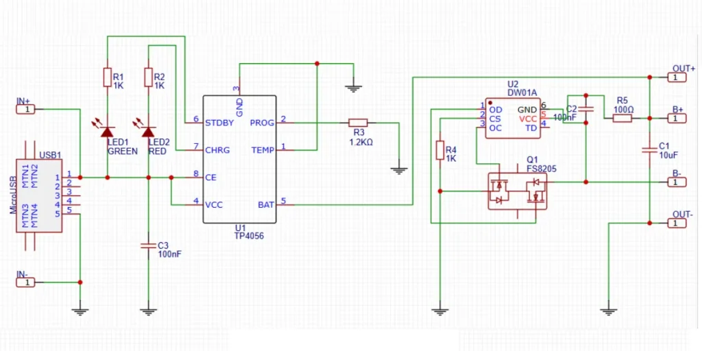
TP4056 Li-Ion Battery Charger Circuit Diagram
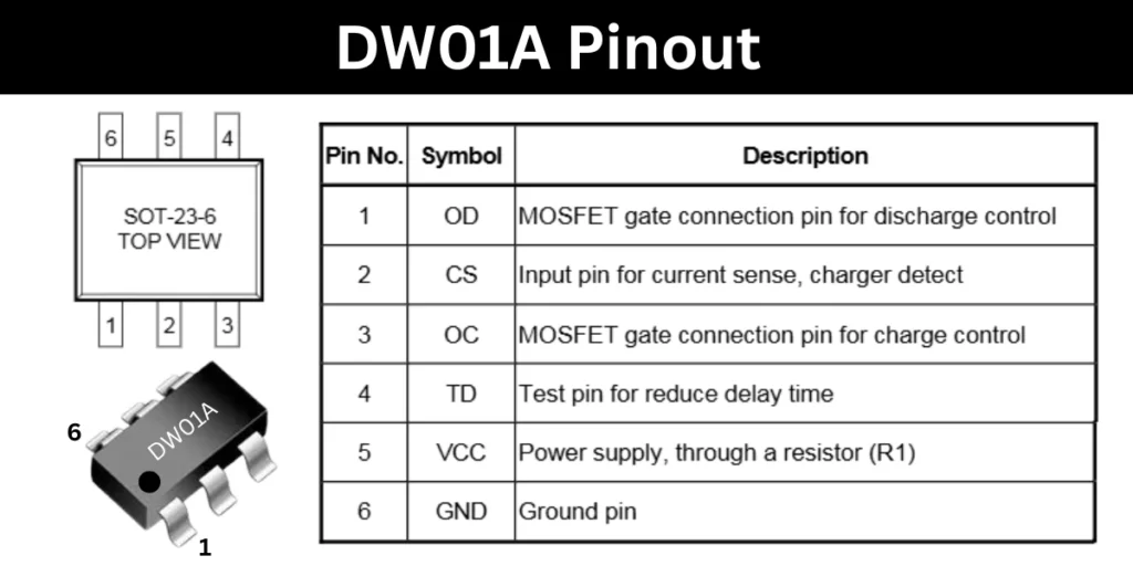
Protection IC Pinout
Construction and Working
The circuit consists of two selections, first one is the charging section and the other is the protection section.
Charging Section Using TP4056 IC
The TP4056 IC is used in this circuit to charge the single cell Li-Ion battery via a Micro USB connector. The IN+ and IN- lines receive 5V input from the USB pins, which is filtered by a 100nF capacitor. The CHRG (pin 7) and STDBY (pin 6) pins drive LED1 (Green) and LED2 (Red) through R1 and R2 (1KΩ) respectively. LEDs are indicate the charging status of the Li-ion battery. This charging status is based on the color of the LED indicated in the board. The red for charging and green for standby or full charge. The PROG pin (2) connects through R3 (1.2KΩ) to ground, setting the charging current (approx. 1A). The BAT pin (5) is connected to the battery positive terminal.
Protection Section Using DW01A IC
The battery protection circuit uses DW01A. Additionally a N Channel MOSFET of FS8205 is added. This protects the battery from overcharge, over discharge and overcurrent conditions. The DW01A monitors battery voltage and current through pins OD, CS, and OC, and controls the gate of the FS8205 to disconnect the load or charger in fault conditions. R4 and C2 provide noise immunity and stability. R5 (100Ω) and C1 (10μF) provide output filtering. The OUT+ and OUT- terminals are the output from the battery to the load.
Features
- CC/CV Charging: Utilizes the TP4056 IC to safely charge lithium-ion batteries using the industry-standard constant-current/constant-voltage method.
- Improved Protection System: In addition to the TP4056, this module integrates the DW01A protection IC and FS8205A dual MOSFET, offering a good battery protection.
Protection Features
- Over-Discharge Protection
- Prevents the battery from discharging below 2.4V.
- If the voltage drops below 2.4V, output is cut off to protect the battery.
- Charging remains possible via the parasitic diode of the discharge control MOSFET.
- Discharge resumes once the battery voltage reaches 3.0V.
- Overcharge Protection
- Charging stops automatically at 4.2V to prevent overcharging.
- Overcurrent and Short-Circuit Protection
- Output is disabled if discharge current exceeds 3A or a short circuit is detected.
- Soft-Start Protection
- Limits inrush current during initial power-up to protect components.
- Trickle Charging (Battery Reconditioning)
- If battery voltage is below 2.9V, a safe trickle current of 130mA is applied.
- Once the voltage reaches 2.9V, the module ramps up to the configured charge current.
LED Indicators
- Red LED – Charging in progress.
- Green LED – Charging complete.
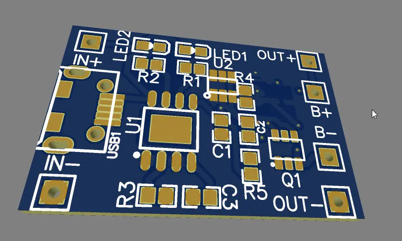
TP4056 li-ion Battery Charger PCB
TP4056 USB-C Charging Module for 18650 Lithium Battery | 3.7V DIY Charger Board with Overcharge Protection 2Pcs
As an Amazon Associate, I earn from qualifying purchases.
🔥 Check Price on Amazon