Are you looking for a simple 12V automatic lead acid battery charger circuit? In this article i’m sharing a DIY project for charging your 12v batteries. This circuit consist of a powerful transistor and zener diode which will controlling the charging process automatically. This given circuit needs minimum number of electronics components to build this. Learn more about the circuit is given below.
Components Required
| Component | Specification | Quantity |
|---|---|---|
| Transistor | TIP41 NPN Power Transistor | 1 |
| Zener Diode | 13.8V | 1 |
| Resistor | 10kΩ, 0.25W | 1 |
| Diode | 1N4007 | 1 |
| Lead Acid Battery | 12V | 1 |
| DC Power Supply | 15V DC Input | 1 |
| Wires/Connectors | As needed | As required |
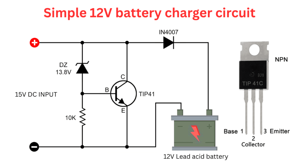
Circuit Diagram
Working Principle
The 15V DC is providing to this charger circuit to charging the 12V lead acid battery. You must need to provide the charge above 13.8V to charging this 12V battery. The zener diode with its voltage of 13.8V is controlling the flow of current through the TIP41C transistor. The battery get charged if the current only passing through this transistor.
If the connected battery voltage is belowe 13.8V the zener diode will conduct and turn on the transistor and charging the battery. Hear the TIP41 transistor is acts like a switch. when a base voltage gets the transistor start to turn ON like a switch and conduct the current flow. This current flows into the battery and charging it.
When battery voltage reaches above 13.8V the Zener diode will no longer conducts. The TIP41 base voltage falls down and it will turning OFF the transistor so it will stopping the charge. The 1N4007 diode is Prevents battery from discharging back into the power supply when input power is off.