In this article I’m sharing the circuit diagram and PCB layout of LED Vu meter using LB1403 or CD1403 IC. This circuit and PCB design is very simple and easy to build at home. A downloadable files also given at the bottom for your reference.
LB1403 LED Vu Meter Circuit
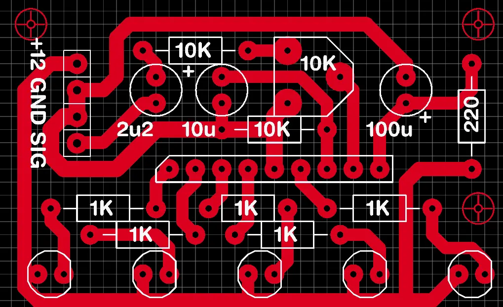
The input voltage to this circuit is 12V DC single supply. The “SIG” marked in the board is the audio input pin, where you need to feed the audio input for this circuit. The components used in this circuit is very less the total cost of the circuit is low compared with LM3915 IC based circuit.
This VU meter circuit contains 5 LED, which is enough for small audio visualization. If you are planning to build a small VU meter this can help you in the next project. Credits: Bijoyts Electro Youtube channel
LB1403 / KA 2284 / an 6884 / BA6124 Audio Level Indicator Pro Audio Level Indicator Module 10 L.E.D. Adjustable DC 5V-9V Electronic Components Electronic Hobby Kit
As an Amazon Associate, I earn from qualifying purchases.
🔥 Check Price on AmazonComponents Required
| No. | Component Type | Value | Quantity |
|---|---|---|---|
| 1 | IC | LB1403 | 1 |
| 2 | Resistor | 10KΩ | 3 |
| 3 | Resistor | 1KΩ | 5 |
| 4 | Capacitor (Electrolytic) | 100µF | 1 |
| 5 | Capacitor (Electrolytic) | 10µF | 1 |
| 6 | Capacitor (Electrolytic) | 2.2µF | 1 |
| 7 | Capacitor (Ceramic/Film) | 220nF (marked 220) | 1 |
| 8 | Header / Pin Connector | 12-pin | 1 |
| 9 | Screw / Wire Terminals | 2-pin | 2 |
| 10 | LEDs | 5 pcs (depending on design) | For level display |