KSA1220 is a PNP transistor comes in TO-126 Package. This epitaxial transistor is best choice for class B amplifier driver stage because of the high transition frequency and current capability. It also used in high frequency amplification also. This article shares the Pinout, Equivalent transistors list and specifications.
What is KSA1220 Transistor?
This transistor is mainly designed for amplifier driver stage because of high voltage and current handling capacity. This PNP transistor can able to handle -120to -160V collector- emitter voltage, this value varies based on KSA1220A variant. This transistor can handle up to 1.2A current, so this transistor is a perfect choice for driver stage in amplifier.
KSA1220 Transistor Pinout
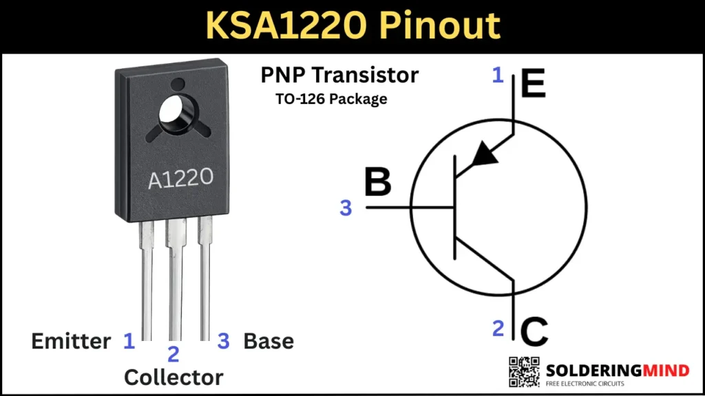
Hold the transistor numbering facing you and the three pins are pointing towards the earth. then count the transistor pin from left to right as Pin1, pin2 and pin3. The corresponding pins order is Emitter, collector and base.
Pinout configuration
| Pin Number | Pin Name |
|---|---|
| 1 | Emitter |
| 2 | Collector |
| 3 | Base |
Specifications of Two Variants
There are some different specifications for KSA1220 and KSA1220A transistor. The A in the suffix represents the high voltage variant transistor. The comparison is given below,
| Parameter | KSA1220 | KSA1220A |
|---|---|---|
| Polarity | PNP | PNP |
| Collector-Emitter Voltage (VCEO) | -120 V | -160 V |
| Collector Current (IC) | -1.2 A | -1.2 A |
| Power Dissipation (PC) | 20 W | 20 W |
| Transition Frequency (fT) | 175 MHz | 175 MHz |
| DC Current Gain (hFE) | 60 to320 | 60 to 320 |
| Package Type | TO-126 | TO-126 |
The major difference is in collector to emitter voltage, the A variant has -160V and the other have -120V. Other parameters are same.
Working Principle of KSA1220
This silicon epitaxial transistor is designed for works as a signal amplification in amplifier driver stage. With the complementary pair of transistor it can work well as a push pull signal amplifier. this transistor is a BJT transistors, so a small current in the base pin turn On the transistor and current passes through emitter to collector.
Complementary Pair
- KSC2690 is the NPN complementary transistor for KSA1220 Transistor. It is designed to work in push pull amplifier circuit.
Equivalent Transistor For replacement
Direct replacement is 2SA1220A, TTA004 and 2SA1907 is also a similar type of transistor can use as a alternative.
You can use KSA1220YSTU but it has low collector emitter voltage.
How to Test Transistor with a Multimeter
- The pins from left to right is Emitter, Collector and base.
- Turn On the multimeter and Place the knobs to the diode testing mode.
- Place the Red probe on the Base pin and black probe on the Emitter pin.
- The reading shows between 0.5 to 0.9V means the junction on the transistor is good.
- You can also check the pins of base and collector the same reading will shows.
- To check the short circuit between the collector and emitter check by placing the probes on the Emitter and collector pins. if their is no continuity means the transistor is good.
Base Resistance Calculation
To safely turn ON the transistor, the current must be regulated by using a resistor. This base resistor value is calculated by using the formula of,
Rb = Vin-Vbe/IB
- Where the Rb is Base resistance
- Vin is input voltage
- Vbe is 0.7v for silicon transistors.
- Ib is Base current
To find the base current Ib the formula is, Ib = Ic/hFE
For switching we are using ”Ic” value is 10 so equation will be Ib=Ic/10
Example calculation
- Supply voltage is 12V
- Load current Ic is 500mA
- Control voltage vin is 5v
Then Ib = 500mA/10 = 50mA
Base resistor Rb = 5V-0.7v/0.05A = 86 ohms so we can use 100 ohms safe resistor.
Advantages and Limitations of KSA1220
| Advantages | Limitations |
|---|---|
| High voltage rating (up to ~120V and 160V for A version) | Not suitable for very high current applications (>1.2A) |
| Good power dissipation (up to 20W with heatsink) | Requires proper heatsinking for high load use |
| High transition frequency (~175 MHz) | Not ideal for very high-frequency RF circuits |
| Compact TO-126 package | Larger than SMD transistors (not suitable for ultra-compact designs) |
| Good gain (hFE) for amplification | Gain varies between batches (needs design margin) |
| Works well in audio amplifier circuits | Not optimized for low-noise precision applications |
| Complementary pair available (KSC2690) | Needs careful biasing in push-pull circuits |
| Reliable and widely used | Becoming less common compared to modern MOSFETs |
| Easy to drive in moderate power circuits | Base current required (less efficient than MOSFETs) |
Applications
- Audio amplifier output stages
- Driver stages
- Push pull configurations