The IRF9540 is also marked as IRF9540n, IRF9540ns, and F9540n. All are the same type of MOSFETSs. This 9540 MOSFET is a P-channel device, with a drain-to-source voltage of -100 V and a continuous drain current rating of 19 A. In this article, I’m sharing the IRF9540 pinout, Equivalent MOSFETs for replacement, and its specifications.
What is the IRF9540 MOSFET?
IRF9540 is a -100V, 19A P-channel MOSFET. This MOSFET is available in TO-220 Packaging. This MOSFET has a very low gate threshold voltage of 2 to 4V. So we can easily integrate this MOSFET with any microcontroller IC. This component is most common in DC-DC converters, H-bridge motor control circuits, and push-pull amplifier designs.
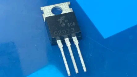
IRF9540 Pinout Diagram

IRF9540 Pin Configuration
To check the pinout configuration of this P channel MOSFET, you need to hold the component number facing you, and the three pins are pointing downward. Then count the pins from left to right as Pin 1, 2, and 3. The corresponding pin name is given in the table below,
| Pin Number | Pin Name |
|---|---|
| 1 | Gate (G) |
| 2 | Drain (D) |
| 3 | Source (S) |
IRF9540 Specifications
- Package Type: TO-220AB
- Drain-Source Voltage is -100V
- Continuous Drain Current is -19A
- Pulsed Drain Current is -72A
- On-State Resistance is 0.117Ω to 0.20Ω
- Gate-Source Voltage is +/- 20V
- Power Dissipation is 150W
- Operating Temperature is -55°C to +175°C
IRF9540 Equivalent MOSFETs
Direct and equivalent replacement MOSFETs are 2SJ380, 2SJ464, 2SJ412, IRF9540PBF, and SIHF9540.
IRF9540 vs IRF9540N: What’s the Difference?
| Specification | IRF9540 | IRF9540N |
|---|---|---|
| Maximum Drain-Source Voltage | -100 V | -100 V |
| Continuous Drain Current | 19 A | 23 A |
| On-State Resistance | 0.200 Ω | 0.117 Ω |
| Maximum Power Dissipation | 150 W | 140 W |
| Gate Threshold Voltage | -2 V to -4 V | -2 V to -4 V |
The IRF9540N has high continuous drain current of 23A and low on state resistance compared with plain IRF9540 MOSFET.
How to Test the IRF9540 MOSFET Using a Multimeter
IRF9540 is a p-channel mosfet and it has an internal diode connected between the drain and source pins. Let’s check the diode drop in one direction using a multimeter. Set the multimeter probe to diode testing mode and place the red probe on the source and the black probe on the drain pin.
A good internal diode shows readings of 0.44 V and 0.7V. Reversing the probes shows an open loop. For checking the switching functionm of the MOSFET, keep the red probe in the source and touch the black probe on the gate pin, then move the black probe to the drain then shows low resistance or continuity reading means it is good. Discharge the gate and check again for confirmation.
Common IRF9540 Failure Symptoms
- The Circuit does not turn ON, when you give the correct gate voltage to the MOSFET.
- MOSFET remains permanently ON, regardless of the gate signal.
- MOSFET stays OFF and fails to conduct current this means no current is passed through the MOSFET.
- Excessive heating is produced during normal operation.
- Drain-to-source short circuit, causing continuous current flow.
- Open circuit between the drain and source: The circuit does not turn ON even when the correct gate voltage is applied.
- MOSFET remains permanently ON, regardless of the gate signal.
- MOSFET stays OFF and fails to conduct current.
- Excessive heating during normal operation.
- Drain-to-source short circuit, causing continuous current flow.
- Open circuit between the drain and source