IRF840 is a powerful N channel MOSFET. This MOSFET can handle Drain to source voltage of 500V and 8A continuous Drain current. This N channel MOSFET is used in DC to DC converter, Motor Controller circuit and Inverter Circuits. In this article we sharing its Pinout, Specifications and Equivalent MOSFET’s information’s.
IRF840 Pinout Diagram and Pin Configuration
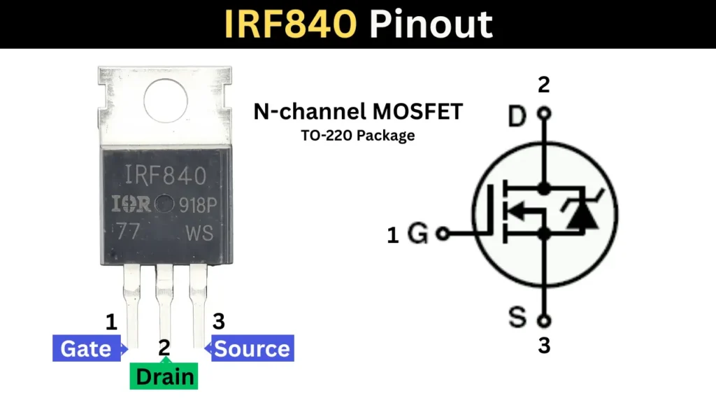
IRF840 MOSFET Pin Configuration
To know the pinout of the MOSFET, you need to keep the numbering facing you and the 3 legs is pointing downward. Then count the pins from left to right as 1, 2 and 3. Pin 1 is Gate, Pin 2 is Drain and Pin 3 is Source.
Also Check – How to Test N channel Mosfet Without multimeter
| Pin No. | Pin Name |
|---|---|
| 1 | Gate (G) |
| 2 | Drain (D) |
| 3 | Source (S) |
Key Specifications and Features
- Type: N Channel MOSFET
- Packaging is TO-220
- Drain to Source Voltage is 500V
- Continuous Drain current is 8A
- Resistance between Drain and source is 0.85 ohms
- Gate Source voltage is +/- 20V
- Minimum Gate to source voltage required is 10V
- Power dissipation is 90W
Also Check – Other Popular N Channel MOSFETS
Equivalent MOSFET’s for Replacement
FQP8N50C, IRF840A, IRF840LC, 2SK2837 and FTK480 are the best and direct equitant to the IRF840MOSFET. You can also use this IRFB13N50A, IRFB17N50L and IRFB9N60A MOSFET which has similar specifications.
✅ Note: Always check the Pinout configuration and characteristics of the MOSFET before replacing with your original components.
Common Applications
- DC to DC converter – The DC to DC conversion need High voltage and current handling MOSFET. This IRF840 can able to handle high voltage DC to DC conversion in high frequency.
- Inverter Circuit – In PWM and sine wave inverter circuit the MOSFET is used for DC to AC conversion by carrying the high voltage and high current through it with matching frequency.
- DC Motor driver need high power handling MOSFET to Increase and decrease its speed by limiting the current. This MOSFET can control the DC motor along with proper control circuit.
How to Test IRF840 Using Multimeter
- Set multimeter to Diode testing Mode.
- Short all three pins using a metal and removes any residual static charge stored in the internal gate capacitance of the MOSFET.
- Connect the multimeter Black (Negative) probe to the Gate and the Red (Positive) probe to the Source, then to the Drain.
- The meter must show open loop or no reading. If reading showing or beep sound detects means the Gate is shorted and MOSFET damaged.
Quick Reference Data for Testing
| Test Scenario | Multimeter Reading | Diagnostics Conclusion |
|---|---|---|
| Any two pins | Continuous beeping / 0.00V | ❌ Defective (Internal short circuit) |
| Source (+) to Drain (-) | 0.4V to 0.9V | ✅ Healthy diode (Forward bias) |
| Drain (+) to Source (-) | OL / No reading | ✅ Healthy diode (Reverse bias) |
| After Gate Trigger | Close to 0V / Low resistance | ✅ Healthy gate (Switches ON properly) |
Driving the IRF840 with a Microcontroller
The Recommended Gate voltage to Turn ON the MOSFET is 10V. The Microcontroller IC can only gives 3-5 V DC output at its pins. So This voltage Can not directly turn ON the MOSFET. To resolve this issue we can use a BC547 or 2N2222 Transistor to amplify the input voltage. The using proper transistor circuit we get 10V easily.
Frequently Asked Questions
Yes, it is a powerful N channel MOSFET, can handle 500V and 8A current.
Need 10V in gate pin to turn ON Fully the MOSFET. In microcontroller based circuit you can use BJT transistor to get the required voltage to drive the MOSFET.
If the 10V DC is applied to the gate pin, it conduct the current flow from drain to source pin. When the gate charge released the current flow get stopped. This is called switching action of the MOSFET.