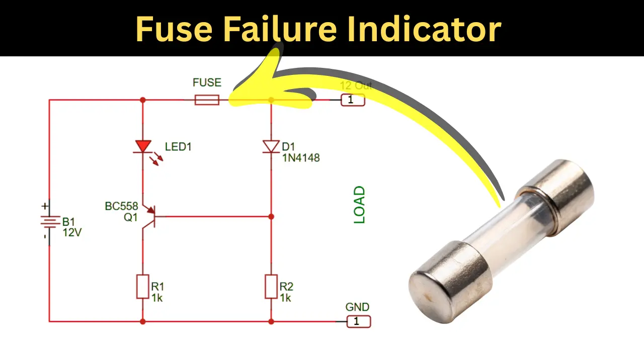
When a Fuse blown or failure happened the circuit gives an indication for it. This is a simple Fuse failure indicator circuit works for 12V DC supply rail. Circuit is deigned using a single transistor and it work perfectly. This article shares the schematics and its working along with components list.
What is Fuse Failure Indicator?
In this circuit, the fuse may get blow under the conditions of overcurrent or a short circuit. In such situations, we may not know that the circuit is not working due to fuse failure. Therefore, this specific circuit is designed to provide an indication when the fuse is blown. Using a simple transistor- and LED-based schematic provides an accurate indication when a fuse failure occurs. This helps in identifying and rectifying the problem easily. It also simplifies the process of troubleshooting complex circuits.
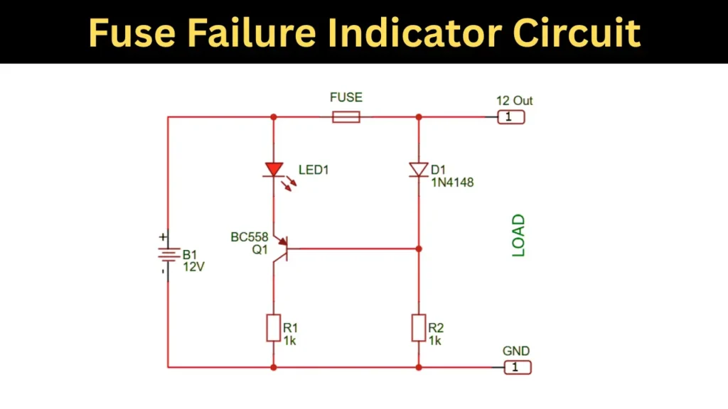
Fuse Failure Indicator Circuit Schematics
Components Required to Build This Circuit
| Component | Label | Specification | Quantity |
|---|---|---|---|
| Battery / Supply | B1 | 12V DC | 1 |
| Fuse | — | Suitable rating (e.g., 1A-5A) | 1 |
| Transistor | Q1 | BC558 (PNP) | 1 |
| LED | LED1 | Standard LED (any color) | 1 |
| Diode | D1 | 1N4148 | 1 |
| Resistor | R1 | 1 kΩ | 1 |
| Resistor | R2 | 1 kΩ | 1 |
| Load | — | As per application | 1 |
| Connecting Wires | — | — | As required |
Circuit Connections
The positive terminal of the 12V supply is connected to one side of the fuse, and the other side of the fuse is connected to the load. The LED is connected from the supply line to the emitter of the PNP transistor of BC558. The collector of the transistor is connected to ground through resistor R1 of 1 kΩ. The base of the transistor is connected to the junction of diode D1 and resistor R2 of 1 kΩ. Diode D1 connects between the load side of the fuse and the base junction, while resistor R2 connects that junction to ground. The negative terminal of the supply is connected to ground, completing the circuit.
Working Principle
The BC558 transistor base pin continuously checking the potential differences across the fuse. The base is connected through the 4148 diode to the positive voltage. so the transistor is in OFF state. If the fuse is blown or broken that time the positive supply through the fuse get stopped and the negative charge pulled from the 1K resistor. Once the negative charge reached to the base pin of transistor turns on the LED and give the Fuse damaged fuse indication.
Applications
- It is used in power supply circuits to quickly identify the fuse failure indication without manual checking of circuit.
- It is useful in industrial control panels for continuous monitoring of circuit protection.
- It helps in automotive electrical systems to indicate blown fuses instantly.
- It is applied in battery-operated devices to ensure reliable operation and easy fault detection.
- It is used in electronic equipment and appliances to simplify troubleshooting and maintenance if fuse is damaged.
- It is helpful in laboratory and testing setups where quick find out fault identification is important.