The DB9 is a 9 pin serial connector. it is used in RS-232 communication for data transfer between the devices like computers, modems and industrial equipment. This article shares the DB9 Pinout of Male and Female connector.
DB9 Pinout Diagram
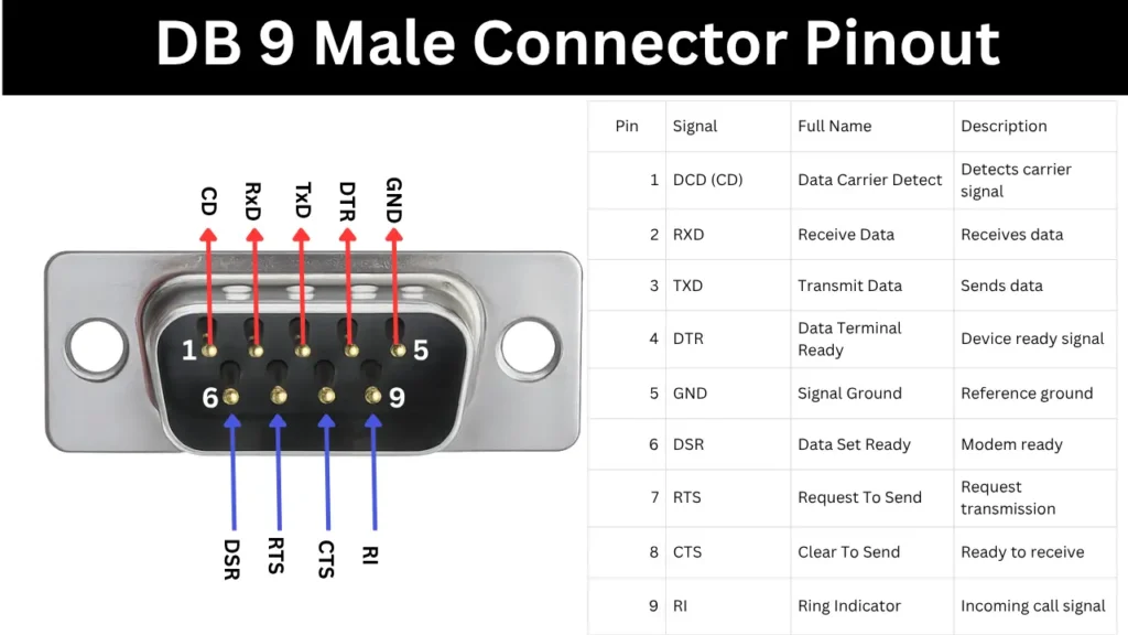
The DB-9 is technically known as DE-9, which is commonly using for RS232 Data transfer. This Male and Female connector comes with 9 pins. Pins of 1 to 5 arranged at the top and 6 to 9 arranges at bottom. This Pinout of Male and female connector is given below,
DB9 Male Connector Pinout
DB9 Female Connector Pinout
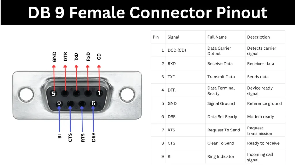
Pinout Configuration
| Pin | Signal | Full Name | Description |
|---|---|---|---|
| 1 | DCD (CD) | Data Carrier Detect | Detects carrier signal |
| 2 | RXD | Receive Data | Receives data |
| 3 | TXD | Transmit Data | Sends data |
| 4 | DTR | Data Terminal Ready | Device ready signal |
| 5 | GND | Signal Ground | Reference ground |
| 6 | DSR | Data Set Ready | Modem ready |
| 7 | RTS | Request To Send | Request transmission |
| 8 | CTS | Clear To Send | Ready to receive |
| 9 | RI | Ring Indicator | Incoming call signal |
RS-232 Communication Basics
The RS232 is an asynchronous serial communication method between Data terminal equipment and data circuit terminating equipment. example of PC connected with modem. It transfer the data through the DB9 or DB25 connectors. The transmitting data will be 1 bit at a time. The length of the cable will be 15Meter and speed will be 20Kbps.
Common Signal Lines in Connector
- XD is Transmitted Data: Sends data from DTE to DCE.
- RXD is Received Data: Receives the data from DCE to DTE.
- RTS is Request to Send: The DTE requests to send data.
- CTS is Clear to Send: DCE allows DTE to send data.