The amplifier have a specific wattage or power output. Exceed the limit of that power delivery capacity the speaker get damaged and burns. The power limit of the power amplifier is indicating as a clip indicator. In this article I’m sharing the Clip indicator circuit for Power amplifier.
Introduction
When the power limit reached or increasing the gain of amplifier to get louder music but the sound get distorted and the speaker get damaged. at the point of distorted sound coming from the amplifier is the clipping area. the clipping circuit helps to protect your amplifier from this condition
when the limit of power amplifier reached that time the light will glow and acknowledged about the power limit. you can also drive a relay through the led line and you can use it as a speaker protection also.
Circuit Diagram
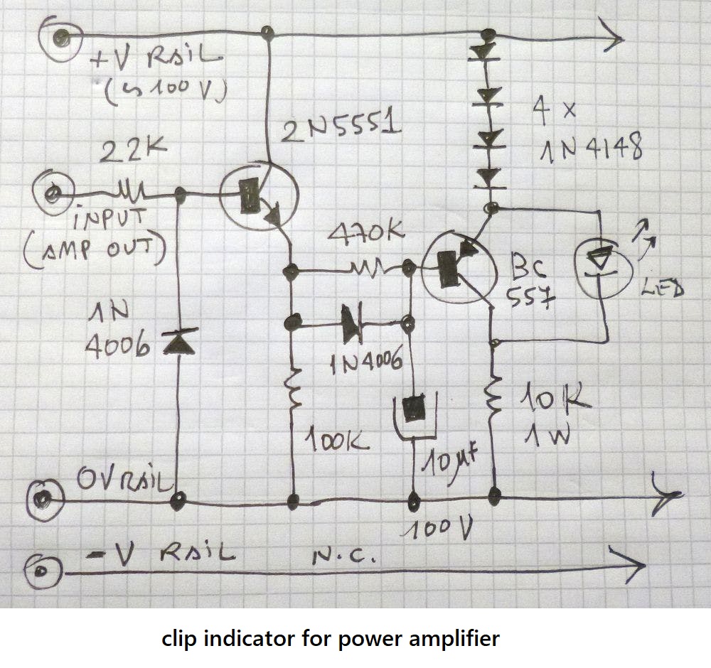
The clip indicator working based on the 2 transistors 2N5551 and a PNP BC557 transistor. The circuit is working in dual power supply +12v – 0v – -12ve supply. You need to connect the audio power amplifier speaker output to the input of the circuit and ground to the circuit ground. when the power limit reached at the time the led get glow.
Basic theory behinds clip indicator
The amplifier producing AC signals in the output if the power limit reached the amplifier producing DC voltage to the output section in that times the coin get heated due to the over dc voltage and it get burn.