This BC549 Transistor based Preamplifier circuit is used to boost the low power audio signal to a stronger signal for further amplification using power audio amplifiers. This BC549 Preamp is a simple and easy audio project that you can build using a breadboard also. So in this article I’m sharing the circuit diagram and additional information of BC549 Transistor based Pre amp.
BC549 Preamp Circuit Diagram
Components Required
| Component | Value / Part Number |
|---|---|
| Q1 | BC549 |
| Q2 | BC549 |
| R1 | 5.6k |
| R2 | 47R |
| R3 | 1k5 |
| R4 | 6.8k |
| R5 | 560k |
| R6 | 33k |
| C1 | 10uF Electrolytic |
| C3 | 10uF Electrolytic |
| C4 | 4.7uF Electrolytic |
| J1 | AUX IN Connector |
| J2 | AUX OUT Connector |
| J3 | GND Connector |
| J4 | GND Connector |
| Power Supply | 9V DC Battery/Adapter |
Function of Each Component in the Circuit
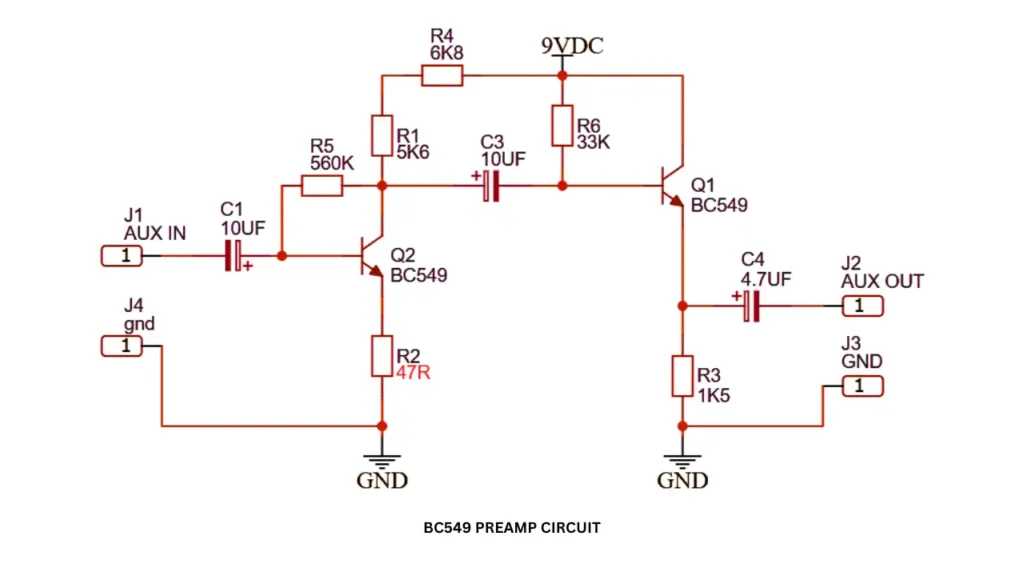
- This circuit works based on the two BC549 NPN transistors. These transistors are working as an amplifier. The first one amplified the initial low strength audio signal and passed to the other transistor. The second transistor boosting the audio signal to strong enough.
- The resistor of 5K6 connected to the collector pin is load resistor which power the transistor and gives signals to the second transistor.
- The resistor 47R connected in the Emitter of the transistor and control the stability and redusing distortion.
- The 6K8 is the biasing resistor, which gives enough biasing voltage to the first transistor of Q1.
- 560K is the feedback resistor connected between the base and collector pin of transistor Q1.
- The two 10uf capacitors are using as a input coupling capacitor, which blocks the entry of DC voltage to the Transistors Base pin.
- The 4.7uf electrolytic capacitor is connected at the end of the stage, which blocks the dc voltage entering into the output device.
How the BC549 Preamp Circuit Works
The BC549 preamp circuit is works by amplifying the low strength input audio signal to stronger signal. The audio signal is passing though the components of Two transistors and capacitor, its audio strength increases with low distortion.
The amplified stronger signal is taking out through the AUX out pin and it is connected to the power amplifier for further amplification. This circuit is powered using a 9V battery or adapter.
Input and Output Capacitor Function
The input capacitor is 10uf and output capacitor is 4.7uf. Both capacitors are 16V electrolytic capacitor, which area used to block the DC voltage and protect the circuit from DC entrance.
Power Supply Requirements
To power this circuit you need to give 9V DC supply. You can use battery as the power source or mini 9V adapter. The circuit needs only 150mA to 500mA current so supply with less current is enough to work this circuit.
Applications of BC549 Preamplifier
- Microphone amplifier.
- AUX audio booster circuit.
- Guitar preamplifier circuit.
- DIY electronic project.