Preamplifier circuits are used to boost the audio signal to stronger. When the audio signals are in a weak condition, they travel through several circuit and cables, which will reduce the audio signal power. So the only solution is to give power to the audio signal for traveling through wires and circuit to get high-quality sound. In this article, I’m sharing the 12V Preamplifier circuit using a diagram, and it is build with the TL072 op amp IC.
Overview of the TL072-Based Audio Preamplifier
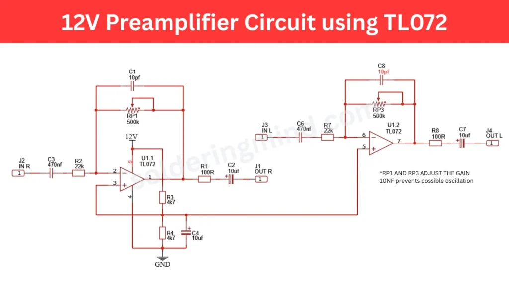
This TL072 IC based stereo pre amplifier works in 12V DC single supply voltage. The op amp IC give good audio quality and we can control the gain of the output by adjusting the 500k pot. For both channel each pot is provided. This circuit is suitable for car audio amplifier and other 12V DC operated amplifier boards which need audio gain boost.
12V Preamplifier Circuit Diagram
Components Required
| Designator | Component | Value / Specification | Quantity | Description |
|---|---|---|---|---|
| U1 | Dual Operational Amplifier | TL072 | 1 | Low-noise JFET input dual op-amp |
| RP1 | Potentiometer | 500k | 1 | Gain adjustment (Right channel) |
| RP3 | Potentiometer | 500k | 1 | Gain adjustment (Left channel) |
| R1 | Resistor | 100R | 1 | Output resistor |
| R2 | Resistor | 22k | 1 | Input resistor |
| R3 | Resistor | 4.7k | 1 | Voltage divider bias resistor |
| R4 | Resistor | 4.7k | 1 | Voltage divider bias resistor |
| R7 | Resistor | 22k | 1 | Input resistor |
| R8 | Resistor | 100R | 1 | Output resistor |
| C1 | Capacitor | 10pF | 1 | Stability capacitor (oscillation prevention) |
| C2 | Electrolytic Capacitor | 10uF | 1 | Output coupling capacitor |
| C3 | Capacitor | 470nF | 1 | Input coupling capacitor |
| C4 | Electrolytic Capacitor | 10uF | 1 | Bias filtering capacitor |
| C6 | Capacitor | 470nF | 1 | Input coupling capacitor |
| C7 | Electrolytic Capacitor | 10uF | 1 | Output coupling capacitor |
| C8 | Capacitor | 10pF | 1 | Stability capacitor |
| J1 | Output Connector | Audio Output (R) | 1 | Right channel output |
| J2 | Input Connector | Audio Input (R) | 1 | Right channel input |
| J3 | Input Connector | Audio Input (L) | 1 | Left channel input |
| J4 | Output Connector | Audio Output (L) | 1 | Left channel output |
| Power Supply | DC Supply | 12V DC | 1 | Circuit operating voltage |
Purpose of Each Component in the Circuit
- The TL072 is the dual op amp IC which is the main part of this circuit, this IC amplify the weak signal to strong signal with high input impedance.
- The Pot RP1 and RP3 is using to adjust the gain (amplification level) of the input audio. By adjusting the pot you will get high volume output with low noise.
- The resistor R2 and R3 is marked as 22K, which uses to cut off the 15Hz frequency and also protect from excessive input current to the IC input.
- The resistor R1 and R8 is rated as 100 ohms which protect the circuit from external load and gives good stability to the output signals.
- The resistor R3 and R4 is 4.7k which creates a voltage divider and provide a virtual ground to the circuit.
- The 470 nF is input coupling capacitor, only allow the AC signal through it and blocks the DC signal from the input source.
- Capacitor C1 and C8 is 10Pf which prevents the high frequency oscillation and maintain the stability of the circuit.
Recommended TL072 Alternatives and Equivalents
If you can not get the TL072 in your market you can choose NE5532, TL082, TL062, RC4558 Op amp IC. The audio quality and power consumption may change if you changes with the TL072. I personally recommended to use original TL072 IC for better performance.
Applications of the 12V TL072 Preamplifier Circuit
- Audio Power Amplifier Front End to boost weak audio signal to strong signal.
- Amplify weak signals from electret microphones or audio pickups.
- DIY home audio systems to boost audio sound output.
- Input stage in audio mixers, equalizers, and tone control circuits by boosting signals