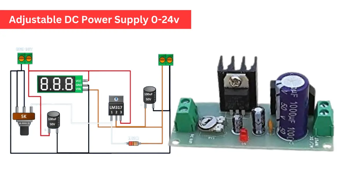
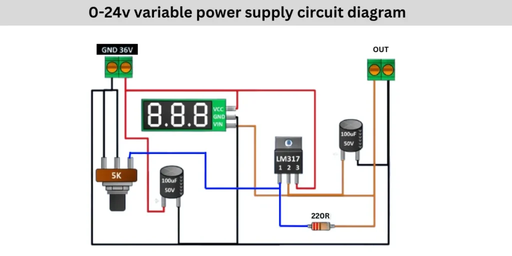
The circuit is an Adjustable DC power supply using LM317 voltage regulator IC to adjust the output voltage from 0V to 24V DC supply. The LM317 Regulator IC is power from a 36V DC input and it will adjust output voltage based on rotation of 5K potentiometer. By rotating the potentiometer you can set the output voltage between 0 to 24V DC voltage.
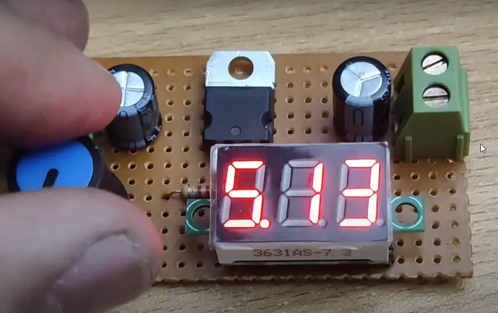
The digital volt meter is optional. This circuit will also works without volt meter. When you are rotating the potentiometer knobs then it will changes the resistance which adjusts the LM317’s output voltage. The capacitors help keep the voltage steady.
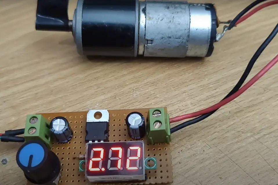
The digital volt meter shows the exact voltage at the output section of the circuit. This circuit is useful for powering different electronic devices and also using for electronic components testing.
0-24v variable power supply circuit diagram
Components Required
| Component | Value/Type | Quantity |
|---|---|---|
| Voltage Regulator | LM317 | 1 |
| Potentiometer | 5KΩ | 1 |
| Resistor | 220Ω | 1 |
| Capacitor | 100µF, 50V | 2 |
| Digital Voltmeter | 3-wire type | 1 |
| DC Power Supply | 36V | 1 |
| Terminal Block | 2-pin | 2 |
| Connecting Wires | – | As needed |
Connection Details
The supply voltage of 36V DC is connected to the circuit through a terminal block. The supply voltage is taken from either a transformer circuit or SMPS circuit. where the positive connection goes to the LM317 voltage regulator input pin of Pin number 3 and the digital voltmeter’s VCC Pin. The ground is shared across the circuit, which is negative supply.
A 100µF capacitor is placed between the input and ground to smoothing the voltage fluctuations. The adjustable pin of LM317 voltage regulator pin 1 is connected to a 5K potentiometer, which controls the output voltage by varying resistance. A 220Ω resistor is connected between the adjustable pin and output pin 2 to set the voltage range.
The output pin of the LM317 delivers the adjustable voltage, which passes through a 100µF capacitor for filtering before reaching the output terminal block. The digital voltmeter’s VIN pin is connected to the output pin and it will display the voltage of the output pin. The ground connection remains common throughout the circuit. By turning the potentiometer the resistance changes and adjusting the output voltage between 0V and 24V DC.