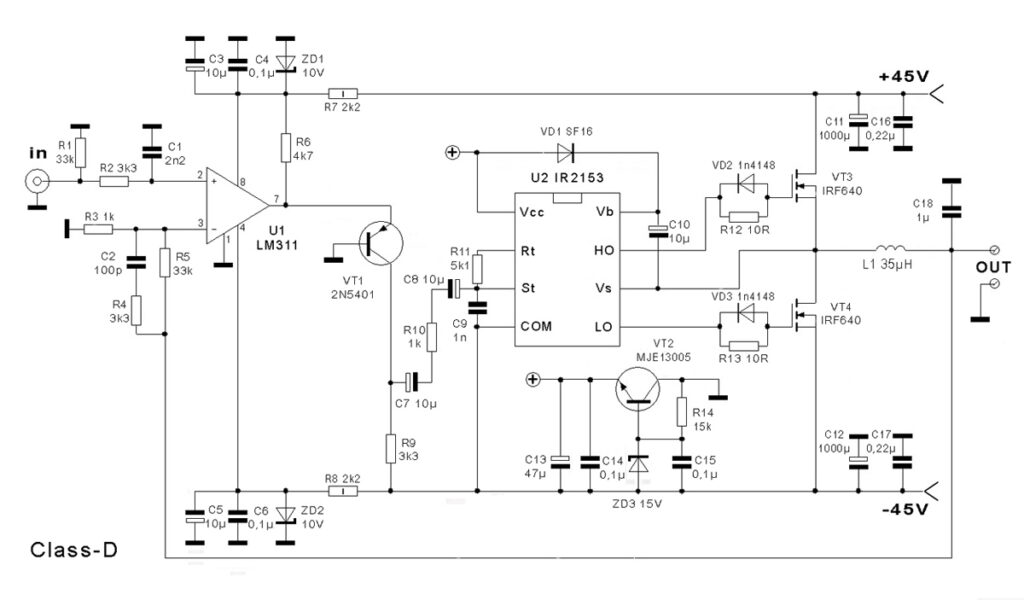
Hello welcome back to the latest topic of 400 W Class D amplifier Circuit diagram and also the PCB Layout. here i’m sharing two circuit with same functions and working. Both of the class d amplifiers are same with few differences. Build your own Class D amplifier.
What is Class D Amplifier
The Class D amplifier or the switching amplifier is an electronic device, in which the amplifying the signals input. This circuits are usually operated by the transistors or Mosfets. The Class D circuits are designed with highest efficiency but it is not quite high fidelity.
The class D amplifier also known as digital amplifiers, working by shifting the sample frequency into extremely high frequency. The major concern with this type of amplifier is they don’t offer same fidelity as like the linear amplifier.
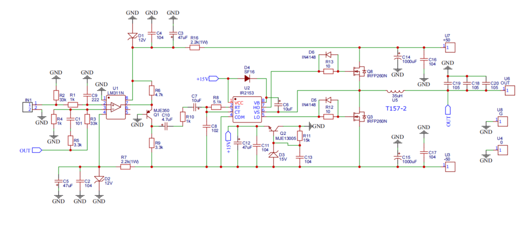
Circuit Diagram
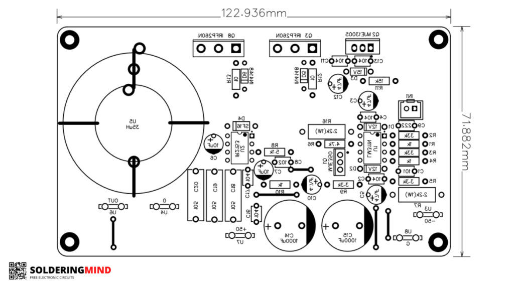
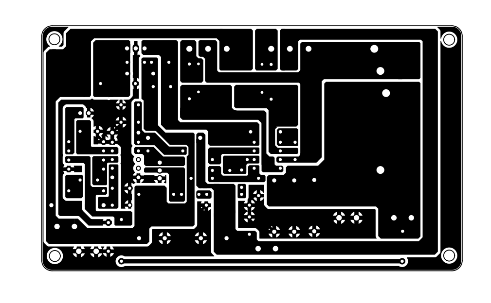
PCB Layout Top
IRS2092 IRS2092S 500W Mono Channel Digital Amplifier Class D HIFI Power Amplifier Board
- Power supply voltage: dual DC power supply ±45–±70V (recommended +-65V power supply, Rated output power: 500W (±65V supply 4 ohm load, distortion degree 1% Efficiency: >= 90% and Signal to noise ratio: 90dB, Total harmonic distortion: 380W (±70 supply 4 ohm speaker
As an Amazon Associate, I earn from qualifying purchases.
🔥 Check Price on AmazonComponents List
- 1×LM311N IC.
- 1×IR2153 IC.
- 1×MJE350 Transistor.
- 1×MJE13005 Transistor.
- 2×IRFP260N MOSFET.
- 2×3.3KΩ resistor 1/4W.
- 2×33KΩ resistor 1/4W.
- 3×1KΩ resistor 1/4W.
- 1×5.1KΩ resistor 1/4W.
- 1×15KΩ resistor 1/4W.
- 2×10Ω resistor 1/4W.
- 1×4.7KΩ resistor 1/4W.
- 2×2.2 – 4.7KΩ resistor 1W.
- 2×Zener Diode 1N4740/ 1N4742 1W (10V/ 12V). 15. 1×Zener Diode 1N4744 15V 1W.
- 2×Zener Diode 1N4148.
- 1× Ultra Fast Diode SF16/ FR107.
- 6×0.1uF (104) capacitor 50V/ 100V.
- 1×0.001uF (102) capacitor 50V/ 100V.
- 1×100pF (101) capacitor 50V/ 100V.
- 1×0.0022uF (222) capacitor 50V/ 100V.
- 3×1uF (105) capacitor 250V/ 400V.
- 3×47uF capacitor 63V.
- 1×4.7uF capacitor 63V.
- 2×10uF capacitor 63V.
- 5×6.3 mm vertical PCB terminal.
- 1×2 pin connecter base 2.54 mm.
- 1×35uH Coil.
- 2×1000uF capacitor 63V.