Build a super easy amplifier circuit using LJ504 amplifier circuit. This circuit is designed by Liadel joshi so it is known as “LJ504”. This article i m sharing the circuit diagram and its PCB layout developed by Bijoyts electro. You can get a downloadable file at the bottom of the article to do yourself.
40 Watts Amplifier Circuit
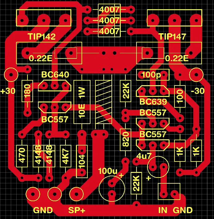
This amplifier is a Darlington pair transistor amplifier, so if you are replace it with normal power transistor wont work. TIP142 and TIP147 is the popular Darlington pair of transistors. some time this transistor availability is difficult. Credits: Bijoyts electro youtube channel
Components Required
| Component | Value / Type | Quantity |
|---|---|---|
| TIP142 | NPN Darlington | 1 |
| TIP147 | PNP Darlington | 1 |
| BC640 | PNP | 1 |
| BC639 | NPN | 1 |
| BC557 | PNP | 3 |
| R1, R2 | 0.22Ω (0.22E) | 2 |
| R3 | 180Ω | 1 |
| R4 | 100Ω | 1 |
| R5, R6 | 1KΩ | 2 |
| R7 | 4.7KΩ (4K7) | 1 |
| R8, R9 | 22KΩ | 2 |
| R10 | 820Ω | 1 |
| R11 | 10Ω 1W | 1 |
| R12 | 470Ω | 1 |
| C1 | 100µF Electrolytic | 1 |
| C2 | 4.7µF Electrolytic | 1 |
| C3 | 100pF | 1 |
| C4 | 0.1µF (104) | 1 |
| D1–D3 | 1N4007 | 3 |
| Power | +/- 30V | 1 |
| Input | IN | 1 |
| Output | SP+ | 1 |
| Ground | GND | 2 |
Inductor Used in the Circuit
The inductor used in the output section is winding is 14 turns with 18SWG Copper wire. Insert the 5.6 Ohms resistor through the inductor and solder it on the PCB. The value of the inductor will be 2uH.