This 12V DC fan controller circuit working with any type of 12V DC fans. This circuit can efficiently control the speed of fan using a simple potentiometer. Adjust the potentiometer in either clock wise or anti clockwise rotation to increase and decrease the speed of Dc fan.
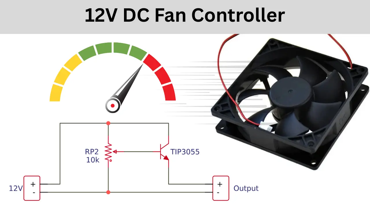
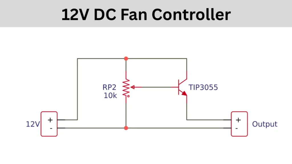
12V DC Fan Controller Circuit Diagram
This circuit is designed with very minimum number of electronic components, so the total cost for building this controller circuit is cheap. First you think about buying expensive DC fan controller boards or build your own circuit for fan. I recommended to build a simple fan controller circuit for your needs.
TIP3055 Transistor Pinout

Circuit Connection and Working
This Fan controller circuit is using TIP3055 NPN power transistor and 10K potentiometer to control the speed of fan easily. The positive supply from the 12V DC supply is connected with the collector pin and one pin of potentiometer. The base of the transistor is connected to the middle pin of the potentiometer. The third pin of potentiometer is connected to the negative supply of 12V.
The emitter pin and the common negative is considered as the output. The out put is connected to the 12V DC fan. when the potentiometer is adjusted the output current also decreased or increased, this will control the speed of connected DC motor.