if your 555 timer Ic get damaged or it is not working properly in a circuit board? In that time you need to Check the IC and its surrounding circuit. In this article i am guiding you about how you can easily test 555 IC using digital or analogue multi meter. The detailed steps are mentioned below. You can follow these steps to find out if the 555 IC is working correct or not.
Before Testing 555 IC Prioritize safety
Always prioritize the safety when working with electronic components. You need to Ensure properly grounded and take precautions to prevent static electricity discharge of electronic components.
Gather the necessary tools
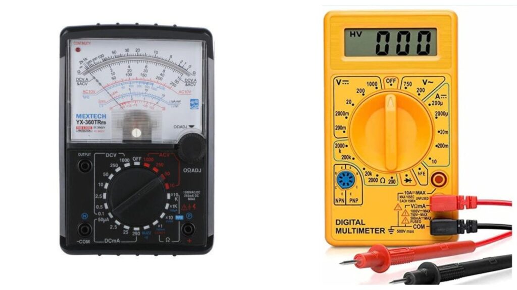
You’ll need a digital or analogue multimeter capable of measuring resistance, voltage, and continuity in a circuit.
Power off Circuit if it is in Working State
Make sure that disconnect any power source connected to the IC 555 and ensure that the circuit is turned off.
Identify the pins of 555 IC
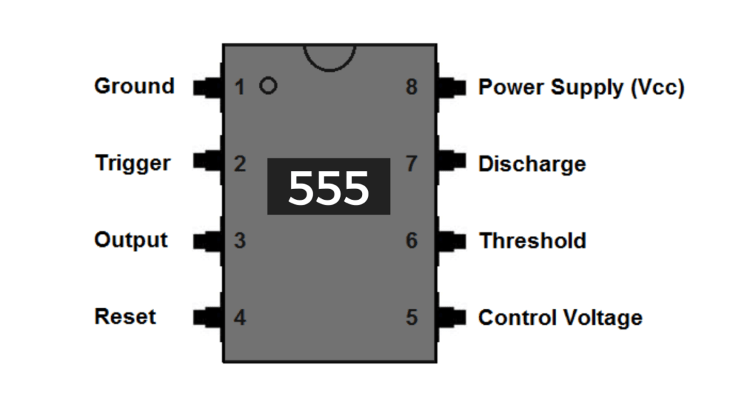
Take a look at the pinout of 555 IC and Familiarize yourself with the pinout diagram of the IC 555. The IC 555 typically has eight pins, numbered 1 through 8. Note the pin configuration, which may vary depending on the package.
Set the multimeter to Resistance Mode
Configure your multimeter to the resistance (ohms) mode. Then you need to test the surrounding resistors values using multimeter. Ensure that the all other resistors connected to the 555 ic is working good with same resistance value.
Test the power supply pins
You need to connect the black probe of the multimeter to the ground pin (usually pin 1) and touch the red probe to the positive supply voltage pin (pin 8). A low resistance reading (close to zero ohms) or continuity indicates a proper connection between the power supply and the IC.
Test the output pin
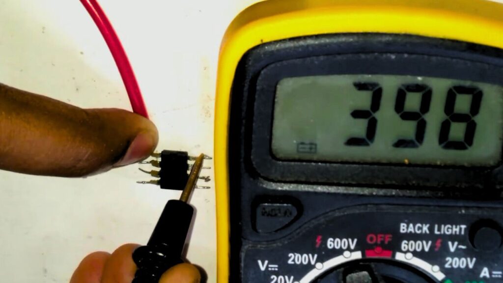
Connect the Multimeter black probe to the ground pin (usually pin 1) and touch the red probe to the output pin (usually pin 3) of 555 timer IC. Switch the multimeter knobs or switch to measure voltage (DC voltage range). Turn on the circuit and observe a stable voltage level (typically high or close to the supply voltage) if the IC is functioning correctly.
Test the control voltage pin
Connect the multimeter black probe to the ground pin (pin 1) and touch the red probe to the control voltage pin (pin 5) of 555 IC. Set the multimeter to measure voltage (DC voltage range). Power on the circuit and measure a voltage close to two-thirds of the supply voltage (around 4.5V if using a 9V supply) if the IC is operating correctly.
Test the timing resistors and capacitors
Disconnect power from the circuit. Set the multimeter to measure resistance (ohms) and measure the resistance of the timing resistors and capacitors connected to pins 6, 7, and 8. Compare the measured values with the expected resistance values specified in the component’s datasheet.
Conclusion
These steps will help you perform a basic test on the IC 555 using a multimeter to assess its functionality. It is important to note that these testing may not uncover all possible issues, but they can provide an initial indication of the IC’s condition such as we can assume the IC is good or bad.