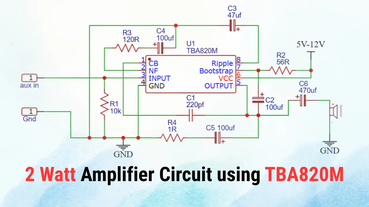
The TBA820M is a low power audio amplifier IC. It is most commonly used in small audio amplification projects. It delivers around 1.2W of output power with low distortion, So this IC based circuit is very best and suitable for battery operated systems and compact audio devices. This given circuit diagram demonstrates how to design a simple and efficient audio amplifier using the TBA820M IC.
Components Required
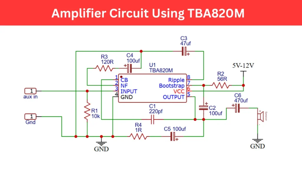
- IC (U1) – TBA820M audio amplifier
- R1 – 10kΩ
- R2 – 56Ω
- R3 – 120Ω
- R4 – 1Ω
- C1 – 220pF
- C2 – 100µF
- C3 – 47µF
- C4 – 100µF
- C5 – 100µF
- C6 – 470µF
- Speaker: 8Ω or 4Ω
- Power Supply: 5V-12V DC
Amplifier Circuit Diagram using TBA820M
Circuit Overview
The circuit uses TBA820M audio amplifier IC (U1) to amplifying the input audio signal, which is the core component of this circuit. It operates with a supply voltage between 5V and 12V, So this circuit is compatible with batteries or small power adapters. The input audio signal is fed through an AUX input and then amplified to drive a small speaker of 2 watt 8ohms rating.
Power Supply and Output
The circuit operates within voltage range of 5V to 12V DC, where, at 9V, it typically provides 700mW to 1.2W output power. The C6 capacitor ensures smooth current delivery to the speaker, reducing low frequency noise. A higher supply voltage increases output power but also heat dissipation, so place a small heatsink on the IC is recommended.
Applications
- Portable audio amplifiers
- Radio and MP3 player speakers
- Intercom and alarm systems
- DIY electronic sound projects