1N4001, 1N4002, 1N4003, 1N4004, 1N4005, 1N4006 and 1N4007 are same type of Diodes and its pinout are same. These diodes look the same, but they have different peak reverse voltage, maximum RMS voltage, and DC blocking voltage. In this article, I’m sharing the Pinout, equivalent, and specifications of the 1N4004 diode.
What is a 1N4004 Diode?
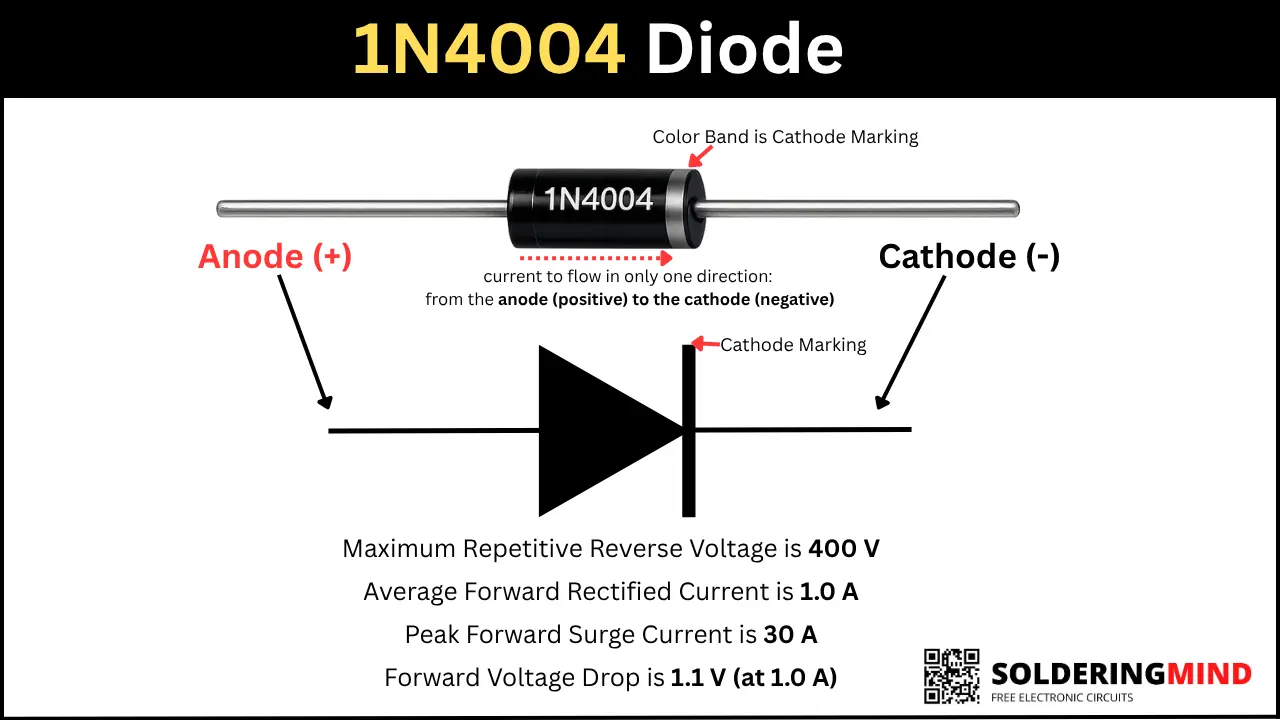
1N4007 is a general-purpose silicon 1A diode. This diode can withstand reverse voltage of up to 400 V; the peak forward surge current is 30A. The forward voltage drop is around 1.1 V. These diodes are commonly used in AC-to-DC conversion in power supply circuits. The diodes are allow the current to flow in only the forward direction or one direction, and reverse voltage is blocked.
1N4004 Diode Pinout
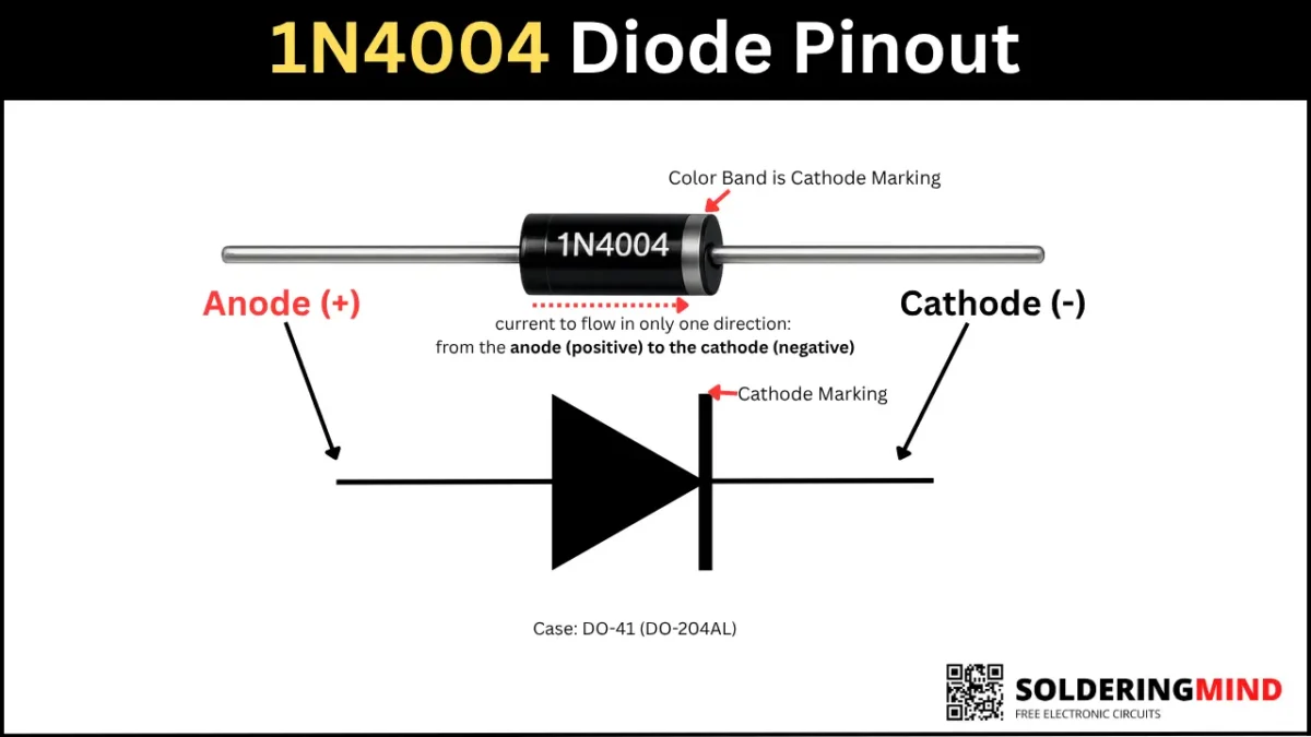
1N4004 Pin Configuration
The Diode pin configuration is easy to memorize because it has two legs, and on one leg a silver marking is present. It is represents the cathode side marking. The detailed pin configuration and forward-bias connection details are given in the table below,
| Pin Name | Description | Function |
|---|---|---|
| Anode (A) | It is the Positive terminal of the diode. | Connect this pin to the positive side of the circuit. The current enters through the anode pin when the diode is in forward biased. |
| Cathode (K) | It is the Negative terminal, identified by the silver/white band on the diode body. | Connect this pin toward the negative side or the load in a rectifier circuit. The Current will exits through the cathode during forward bias. |
1N4004 Diode Specifications
- Package: DO-41 (axial lead, molded plastic)
- Maximum Repetitive Reverse Voltage is 400 V
- Average Forward Rectified Current is 1.0 A
- Peak Forward Surge Current is 30 A
- Forward Voltage Drop is 1.1 V (at 1.0 A)
How Does the 1N4004 Diode Work?
The diode has two terminals and which is marked as anode and cathode. The anode is positive side and cathode is negative side. The diode only works in the forward direction, like a one-way valve, and only allows current to flow in one direction. Like the way this diode conducts current only in one direction, which is the forward direction. If the diode is connected in the reverse direction in a circuit, it will block the flow until it reaches its reverse voltage limit of 400 V. Above 400 V, the diode damaged or explodes.
1N4004 Equivalent Diodes
You can use direct replacement from the same family of 1N4005, 1N4006, and 1N4007. These are high-reverse-voltage diodes. So you can use these instead of 1N4004 diodes.
Difference Between 1N4004 and Other 1N400x Series Diodes
| Diode | Maximum Repetitive Reverse Voltage (VRRM) | Main Difference |
|---|---|---|
| 1N4001 | 50 V | Lowest reverse voltage rating. |
| 1N4002 | 100 V | Higher reverse voltage than 1N4001. |
| 1N4003 | 200 V | Suitable for medium-voltage applications. |
| 1N4004 | 400 V | Good balance of voltage handling and cost. |
| 1N4005 | 600 V | Higher reverse voltage capability. |
| 1N4006 | 800 V | Suitable for higher-voltage circuits. |
| 1N4007 | 1000 V | Highest reverse voltage rating in the series. |
How to Test the 1N4004 Diode Using a Multimeter
To test the 4004 diode using a multimeter, first you need to disconnect it from the circuit board. Then turn the multimeter ” ON ” and set the knob to diode testing mode. Then connect the red probe to the anode and the black probe to the cathode pin. A healthy silicon diode should display a reading between 0.5 V and 0.8 V. Reverse the probes, and it will show OL (open loop). More clear steps to testing diodes are given below,
| Step | Procedure | Expected Reading |
|---|---|---|
| 1 | Disconnect the 1N4004 diode from the circuit board to avoid false readings. | Diode is isolated from the circuit. |
| 2 | Turn ON the multimeter and set the selector knob to Diode Test mode. | Multimeter is ready for diode testing. |
| 3 | Connect the red probe to the Anode (A) and the black probe to the Cathode (K). | A healthy silicon diode should read 0.5 V to 0.8 V. |
| 4 | Reverse the probes (black to Anode, red to Cathode). | The display should show OL (Open Loop) or Over Limit, indicating no current flows in reverse bias. |
| 5 | Interpret the results. | 0.5–0.8 V (forward) + OL (reverse) = Good diode. OL in both directions = Open diode. 0 V or very low in both directions = Shorted diode. |
Typical Applications of the 1N4004 Diode
- Diodes are used in AC to DC converter circuit to convert alternating current to direct current.
- Battery charger circuit.
- Relay fly back protection.
- Revers polarity protection.
- LED circuits and DIY projects.