In this article I’m sharing an easy and helpful electronic project to do yourself. A high quality tone control board based on the vintage AKAI 1030 stereo receiver. This circuit used here is a high gain type, so the level of the input signal must be adjusted very carefully to avoid audio signal distortion. Remember that Proper signal level management will help you to maintain clear and balanced audio output.
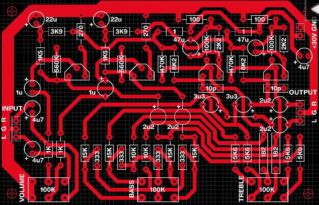
Circuit Diagram
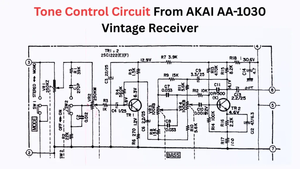
The transistor used in this circuit is 2SC1222. This transistor is very difficult to purchase from your electronics market nowadays. So, I used a BC549 transistor as a replacement for 2SC1222. You can also try other compatible transistors such as BC547, BC548, 2N2222, C1815 or KSC1845. Before replacing the transistor make sure to adjust the pin configuration, because the PCB is designed for a CBE type of pin layout.
Circuit to Avoid Humming Sound
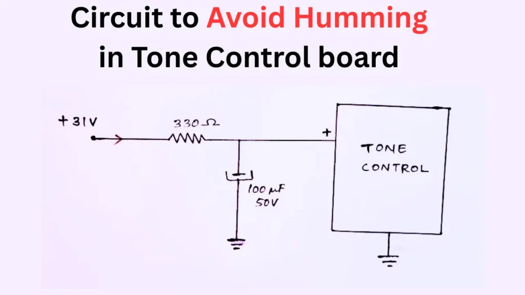
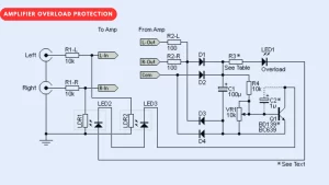
The recommended power supply voltage for this circuit is 30V DC single supply rail. If any humming sound is happening you can use the humming reducer circuit, and use a good quality, well filtered power supply to avoid maximum humming sound. You can use the RC filter circuit shown in the images to reduce the hum. The circuit will operate properly with a minimum of 24V DC supply. The complete circuit diagram is given here, and also a downloadable PDF is also provided below. Credits: Bijoyts Electro Youtube channel