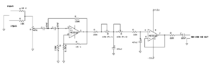
This article describes the Pre amplifier circuit, PCB layout and Connection details. This Pre amplifier circuit is build with LA3161 IC and C1815 Transistors. This circuit is common in old cassette player amplifier boards.
Circuit Diagram
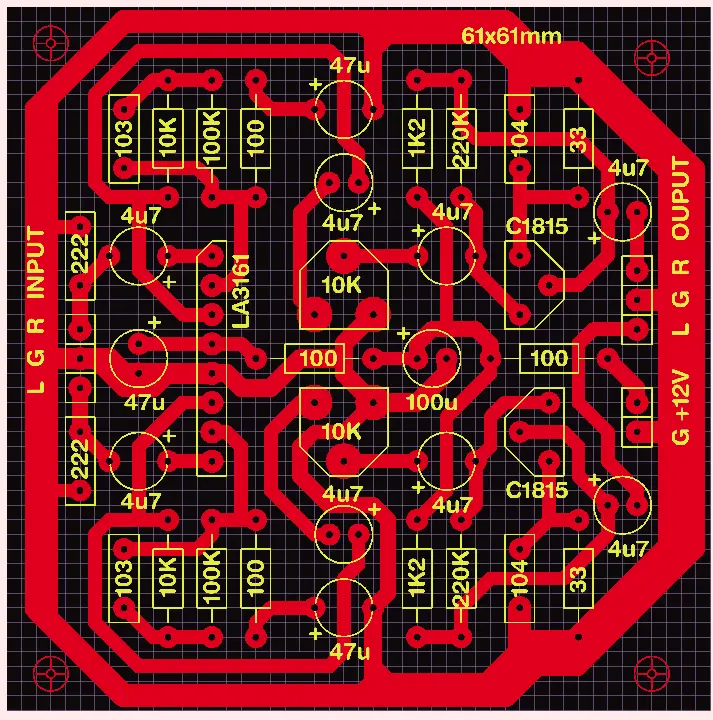
The gain of this board can be adjusted using the given 10k preset. Bea aware about the over gain, it will destroy the total audio quality so set the gain accordingly.
The 222 pf capacitor in the input section is used for noise filtration. So you can replace that with 102 pf capacitor for working with more high frequency response. The quality of the Tape Head determines the sound quality. So use a good quality tape head.
Components Required
| No | Component | Value / Part Number | Quantity |
|---|---|---|---|
| 1 | IC | LA3161 Audio Pre-Amplifier IC | 1 |
| 2 | Transistor | C1815 (NPN) | 2 |
| 3 | Transistor | 2N2222 / A2222 (NPN) | 2 |
| 4 | Resistor | 10KΩ | 4 |
| 5 | Resistor | 100KΩ | 2 |
| 6 | Resistor | 220KΩ | 2 |
| 7 | Resistor | 1.2KΩ (1K2) | 2 |
| 8 | Resistor | 100Ω | 4 |
| 9 | Resistor | 33Ω | 2 |
| 10 | Capacitor (Electrolytic) | 4.7µF (4u7) | 8 |
| 11 | Capacitor (Electrolytic) | 47µF | 4 |
| 12 | Capacitor (Electrolytic) | 100µF | 1 |
| 13 | Capacitor (Ceramic) | 103 (10nF) | 2 |
| 14 | Capacitor (Ceramic) | 104 (100nF) | 2 |