The KY-040 rotary encoder is a device that can be used to detect the rotational movement of a shaft. It is commonly used in DIY electronics projects to control things like volume or brightness, or as a user input device.
Also Check : Rotary Encoder Working
Connection Diagram
Rotary Encoder
A rotary encoder, also known as a shaft encoder, is an electromechanical device that can be used to detect the rotational movement or position of a shaft. It is commonly used in various applications, including control systems, automation, and user input devices.
Rotary encoders typically consist of a rotating shaft, a code disk, and optical or magnetic sensors. As the shaft rotates, the code disk rotates along with it, generating a series of pulses or digital signals that are proportional to the rotation angle of the shaft. These signals are then interpreted by an electronic circuit to determine the position of the shaft.
Rotary encoders can be classified into two main types: absolute and incremental. Absolute encoders provide a unique digital code for each specific shaft position, while incremental encoders only provide information about the change in shaft position since the last reading.
Rotary encoders are widely used in various industries, including automation, robotics, and consumer electronics. They are known for their high precision, reliability, and versatility, making them a popular choice for a wide range of applications.
KY040 Rotary Encoder With Arduino
Arduino Uno or Arduino nano is an open-source electronics platform based on simple software and hardware. With the help of an Arduino board and the KY-040 rotary encoder, you can build interactive projects that respond to the rotational movement of the encoder. You can also use the encoder to control various functions in your project by rotating the shaft.
To use the KY-040 rotary encoder with an Arduino board, you’ll need to connect the pins of the encoder to the appropriate pins on the Arduino board. You’ll also need to write code that reads the signals from the encoder and performs some action based on the movement of the encoder. This code will be written using the Arduino Integrated Development Environment (IDE) and the C programming language.
Connecting a KY-040 Rotary Encoder to an Arduino Board
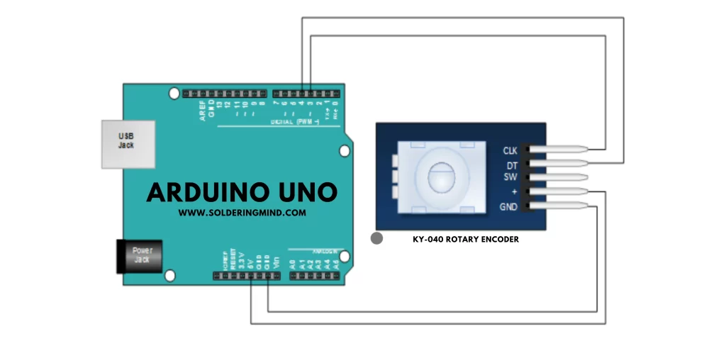
Here’s a typical connection diagram for connecting a KY-040 rotary encoder to an Arduino board:
KY-040 Pin 1 (GND) -> Arduino GND
KY-040 Pin 2 (VCC) -> Arduino 5V
KY-040 Pin 3 (DT) -> Arduino Digital Pin 2
KY-040 Pin 4 (CLK) -> Arduino Digital Pin 3
KY-040 Pin 5 (SW) -> Arduino Digital Pin 4 (optional)
Note that the connections for the switch (SW) pin are optional, as not all KY-040 encoders have a switch. If your encoder does have a switch, you can connect it to an input pin on the Arduino board to detect when the switch is pressed.
Once the connections are made, you’ll need to write a program that uses the Arduino’s digital inputs to read the signals from the encoder and respond to the rotational movement of the shaft. A simple example of an Arduino sketch that uses the KY-040 encoder is provided below:
Programming Code
#define ENCODER_DT 2
#define ENCODER_CLK 3
#define ENCODER_SW 4

volatile int encoderPos = 0;

void setup() {
  pinMode(ENCODER_DT, INPUT);
  pinMode(ENCODER_CLK, INPUT);
  pinMode(ENCODER_SW, INPUT_PULLUP);
  attachInterrupt(digitalPinToInterrupt(ENCODER_DT), encoderTurn, CHANGE);
  attachInterrupt(digitalPinToInterrupt(ENCODER_CLK), encoderTurn, CHANGE);
}

void loop() {
  // Use the encoderPos variable to control your project
}

void encoderTurn() {
  if (digitalRead(ENCODER_CLK) == digitalRead(ENCODER_DT)) {
    encoderPos--;
  } else {
    encoderPos++;
  }
}
This sketch uses interrupt-based handling to detect changes in the rotational movement of the encoder. The encoderTurn function is called whenever a change is detected in the signals from the encoder, and the encoderPos variable is updated accordingly. You can use this variable in your code to respond to the rotational movement of the encoder.
LED Brightness Controlling Using KY-040 and Arduino
Here is an example Arduino sketch that uses a KY-040 rotary encoder to control the brightness of an LED:
#define ENCODER_DT 2
#define ENCODER_CLK 3
#define LED_PIN 9

volatile int encoderPos = 0;

void setup() {
  pinMode(ENCODER_DT, INPUT);
  pinMode(ENCODER_CLK, INPUT);
  pinMode(LED_PIN, OUTPUT);
  attachInterrupt(digitalPinToInterrupt(ENCODER_DT), encoderTurn, CHANGE);
  attachInterrupt(digitalPinToInterrupt(ENCODER_CLK), encoderTurn, CHANGE);
}

void loop() {
  analogWrite(LED_PIN, map(encoderPos, 0, 100, 0, 255));
}

void encoderTurn() {
  if (digitalRead(ENCODER_CLK) == digitalRead(ENCODER_DT)) {
    encoderPos--;
  } else {
    encoderPos++;
  }
  encoderPos = constrain(encoderPos, 0, 100);
}
This sketch uses the same interrupt-based handling as the previous example, but instead of using the encoderPos variable to control some aspect of the project, it uses it to control the brightness of an LED connected to pin 9. The map function is used to scale the encoderPos variable from a range of 0-100 to a range of 0-255, which corresponds to the PWM range of the LED. The constrain function is used to ensure that the encoderPos variable stays within the specified range of 0-100.
With this code, you should be able to rotate the shaft of the KY-040 rotary encoder to adjust the brightness of the LED. By modifying the code, you can use the encoder to control other aspects of your project as well.