Hi friends after a long interval I would like to share an interesting circuit of a low pass subwoofer filter board. This subwoofer filter board is based on a single ic of PT2351, Nowadays most of the remote kits are composed with this ic subwoofer circuit. PT2351 Subwoofer circuit is very easy to build on your dotted PCB or normal copper clad by PCB etching Method. This subwoofer low pass filter have some advantages of
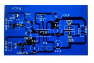
- Adjustable and fixed frequency as per our interest is possible by changing the capacitor values.
- Working voltage is 12v DC single power supply
- easily work with DC adapter
PT2351 Datasheet – Princeton Technology
pt2351 18 subwoofer crossover low pass filter cheap utilizing CMO technology having a slope rate of -12 DB . using an external capacitor and other components the role of point can be adjusted, to meet your needs or requirements. pt2351 ic has low distortion and high input impedance, low output impedance design the application circuit and pin assignment are optimized for easy PCB layout and cost saving benefits.
Features
- CM technology
- Single power supply from 3 volt to 9 volt
- Second order low pass filter design with slope rate -12 DB
- Low output impedance
- List external components
- 2 channel input are mixed to a single subwoofer output
- Available in 8 pin SO or dip package
PT2351 pinout
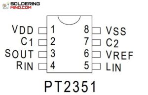
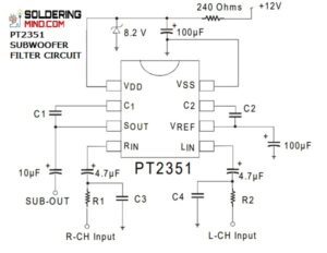
PT2351 subwoofer filter circuit diagram
- SG 3525 PWM ic based Power Inverter – Circuit and PCBThe sg 3525 ic is a PWM producing ic. That could be available in all electronics… Read more: SG 3525 PWM ic based Power Inverter – Circuit and PCB
- TDA2030 Bridged Subwoofer amplifier circuitSubwoofer amplifier – The single ic can produce only the maximum power of 20 watts. in… Read more: TDA2030 Bridged Subwoofer amplifier circuit
- Current limiting resistor: Glow LED from 230v ACcurrent limiting resistor for Glowing led from ac: The LED (light emitting diode) the LED operating… Read more: Current limiting resistor: Glow LED from 230v AC
- 1000 watts audio amplifier circuit1000 watts audio amplifier circuit using TTA 1943 and TTC 5200 transistor. These transistors are very… Read more: 1000 watts audio amplifier circuit
- Subwoofer Amplifier and SubwooferSubwoofer? What is mean by sub? how does the subwoofer work? know detailed about sub-woofer and… Read more: Subwoofer Amplifier and Subwoofer
- LM386 IC Audio Amplifier CircuitLM386 ic Audio amplifier circuit diagram and it’s working. Here we are going to discuss the… Read more: LM386 IC Audio Amplifier Circuit
- Amplifier Circuit – 50 Watts Amplifier Using TDA2030Amplifier circuit using Tda2030 and Tda2050. A single TDA2030 IC can deliver up to 15 watts… Read more: Amplifier Circuit – 50 Watts Amplifier Using TDA2030
- Low pass filter circuit for subwoofer amplifier.Low pass filter circuit using NE5532 opamp: The subwoofer amplifier needs a filter board to drive… Read more: Low pass filter circuit for subwoofer amplifier.
- 3.7 v li-ion battery charger circuit using lm3583.7 v li-ion battery charger circuit using lm358. it’s a simple circuit that will effectively charge… Read more: 3.7 v li-ion battery charger circuit using lm358
- Automatic Lead-acid Battery Charger – 12v 5a battery chargerAutomatic Lead acid battery charger – This is a very simple and effective circuit for charging… Read more: Automatic Lead-acid Battery Charger – 12v 5a battery charger

Circuit please hobby
150hz sub filter circuit
Pdf file download