Here is a quick analysis of the rotary encoder pinout connection and its working principle. The Rotary encoder from its name is clear that the rotation is encoded and get the output signals from it. Here I am discussing the common KY-040 Rotary encoder pinout connections and its working.
The output data of the rotary encoder is from its rotation speed and the direction of rotation. This Rotary encoder can be used in Controlling the Servo and stepper motor speed. The 360 Degree rotation of this rotary encoder is the great advantage. So you can use this for Volume controlling in audio amplifiers.
How is the Rotary encoder working?
Before starting to know about the working of a rotary encoder You need to know the internal structure and how it will send data to the output pins.
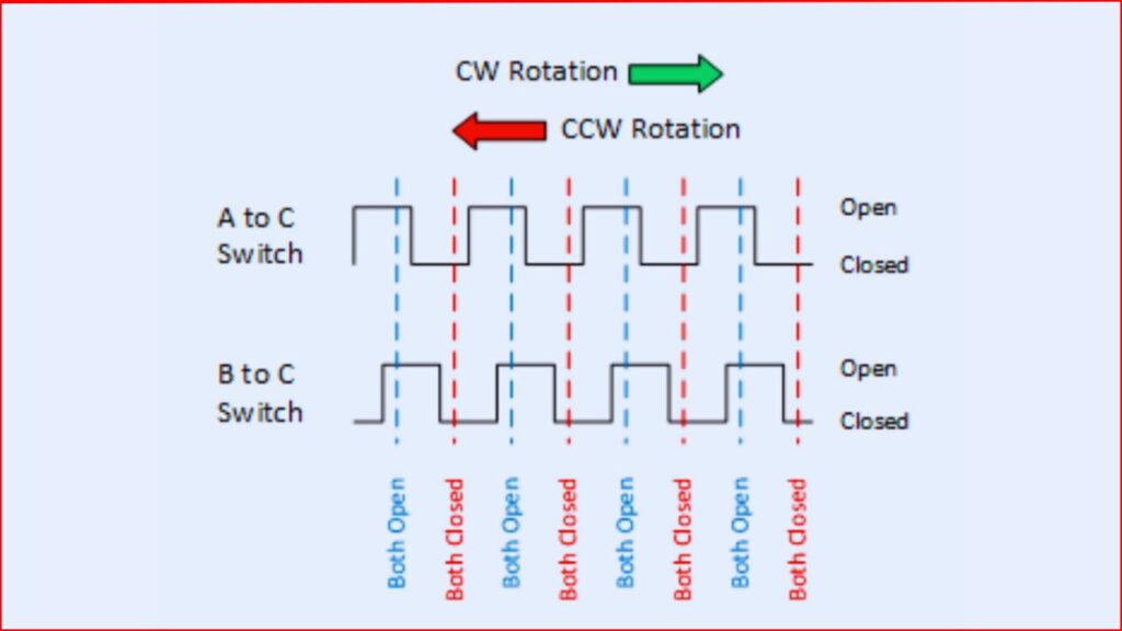
KY-040 Rotary encoder having 30 number of positions aligned on a circular PCB internally. There are three pins available in the rotary encoder, when the encoder is rotating clockwise the both switches inside of the encoder get opened. And closed in anti-clockwise rotation.
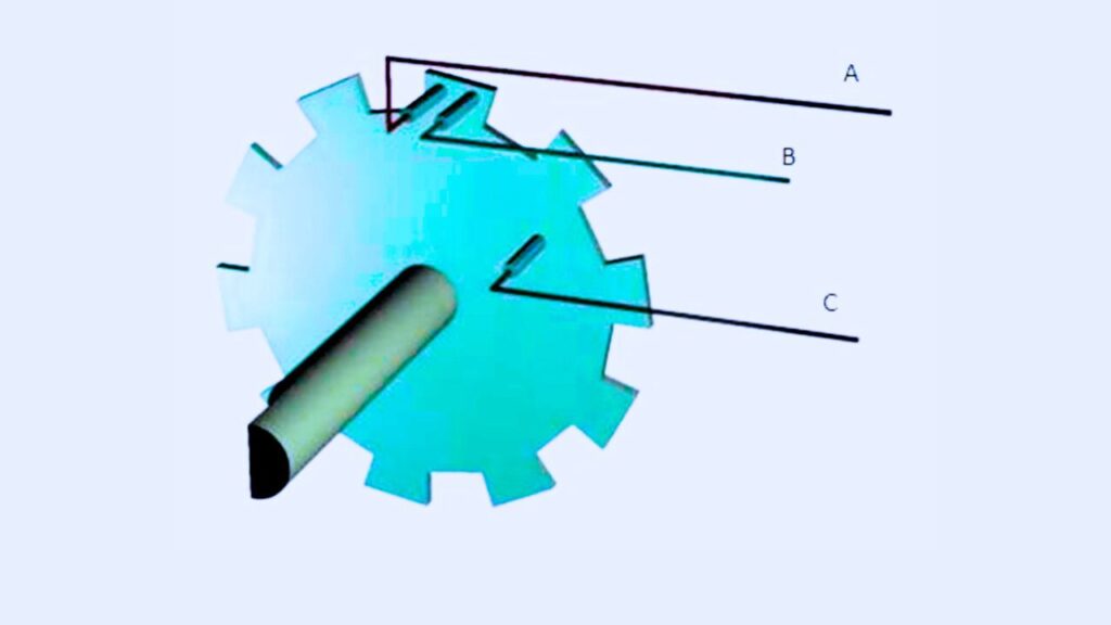
For more clarification The three pins of this rotary encoder are considered as A, B and C. The C is the ground pin. When the encoder is rotating clockwise the A and C get coming to the connection.
On anti clockwise rotation the B will be connected to the C pin. This will make as a wave form and it is represented in the given above figure
KY040 Rotary Encoder Pinout
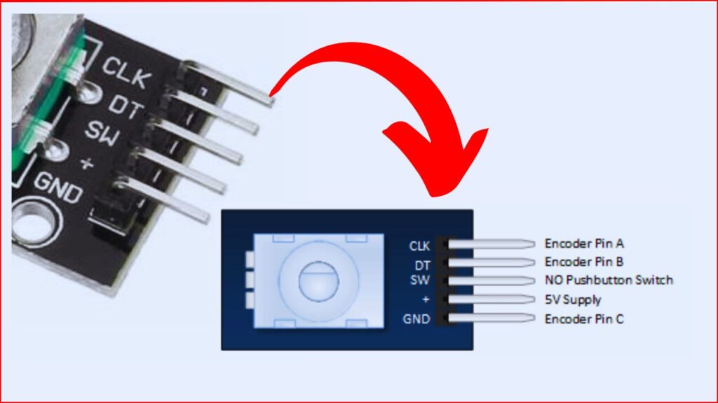
| Pin Number | Function | Description |
|---|---|---|
| 1 | CLK | Clock output Pin (Quadrature output signal A). |
| 2 | DT | Data output Pin (Quadrature output signal B). |
| 3 | SW | Push button switch output. |
| 4 | + | Vcc (Power supply voltage, +5V DC). |
| 5 | GND | Ground (GND) |
- CLK – The Clock pin will produce the square wave signal and the microcontroller will sensing rotary movement based on this produced waves.
- DT – This pin also also produce square wave. It helps to detect the speed of rotation and direction of movement.
- + pin – The pin is act as a input voltage connector. A 5V Dc is connected to it for working.
- SW – This pin is act as a switch. When punching the encoder knobs it will act like a push button.
- GND – Connecting ground of the supply ( negative supply ).