This preamplifier circuit is built with an op-amp ic of TL072. The noise is one of the main problems in high-end audio systems. This circuit is a Hi-fi audio preamp used in the new audio systems. The low noise is one of the main characteristics of this circuit.
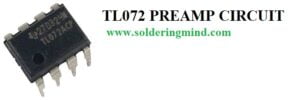
So, in this article, I’m going to explain how to make a preamplifier circuit using Tl072 op-amp ic. Most of the audio devices that not produce power output signals from the audio source board. so this problem will lead to low output sound when amplification through the amplifier.
Then we included the first stage of the preamplifier board to gain more signals from the audio source. This issue is mainly happening with the mic amplifier. you can also use this preamplifier for the microphone. Also, check other related audio amplifier circuits.
- LM386 ic audio amplifier circuit
- TDA1553 car stereo audio amplifier circuit
- LM358 microphone preamp
- NE5532 subwoofer low pass filter circuit
Low noise audio preamplifier circuit and explanation
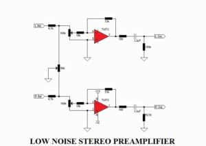
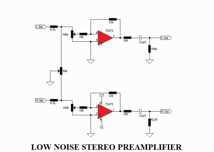
The preamplifier is TL072. Is a dual op-amp plastic packaged ic. This circuit is designed as a stereo preamp. It is a preamplifier with balanced output signals will be provided.
The connected 100k pot on the left and right input of the circuit will allow adjusting the input signal. The 50k pot allows you to balance the left-right signals.
The main advantage of this circuit is
- Build with a high-quality ic tl072
- Few numbers of external components.
- The working voltage is from 12v to 30v dual supply.
- Hifi pre-amplifier circuit.
- stereo preamp.
Components required
- Tl072 ic -1
- 100k pot -2
- 50k pot – 1
- 4.7k resistor – 2
- 15k resistor – 2
- 33k resistor – 2
- 100-ohm resistor – 2
- 100k resistor – 2
- PCB – 1
- connecting wires
Pre-amplification of audio input from MIC
Connect the mic wire on the left input or right input. Adjust the liner pot to increase the amplifier sound gain. Then the boosted mic audio signals will get on the output stage.


Do you have the pcb layout for this préamplifier?
Yes i have
Hy
Very interresting diagram.
May you confirm the lost voltage or db reduction when balance is centered ?
I hope 15k or 33k resistor value could be change to achieve my gain, isn’t it ?
Regards
Larry