This is a very interesting circuit diagram for make full ambiance in your bed room. The LED fade in and out circuit for bed side table lamp. The circuit contains a push button but additionally i added a PIR motion sensor for fully automatic operation. so go through the circuit and enjoy.
The circuit is working based on a op amp ic LM324. You can easily adjust the Fade in timing by changing the 75K resistor connected with the 9 the pin of the IC. The circuit is very useful for bed room lighting and also using for automobile interior lighting.
Circuit Diagram
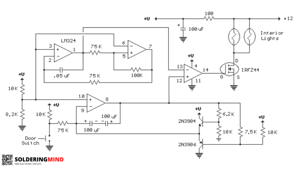
From the circuit it is working based on a door switch so i just going to make some changes in the circuit for home bedroom lamp automation. the door switch is acting as the triggering section to fade in and out the output led circuit.
Working
The circuit will works as led fade in and fade out, for more clearly says that the connected led lights will turn on slowly ( less brightness to high brightness ) and it also slowly turn off. This circuit is perfectly suitable for the bedroom lamp and also automobile interior lights. The circuit diagram is based on the LM324 low power op amp which consumes around 3mA of current for working. So won’t bother about the current usage of the circuit.
The top two op amps in the circuit ( pin 1,2,3 and 5,6,7 ) will forms a triangle wave oscillator. It running around 700Hz. While the lower opamp in the circuit ( pin 8,9,and 10 ) generating a 5 second ramp. The switch will decide the selection of up and down circuit. The 2N3904 and 2N3906 transistor and associated resistor will limit the ramp voltage.
These two signals ( 700 Hz triangle wave form and 5 second ramp ) is applied to the fourth op amp pins of 13 and 12. This section will serves as a generating varying duty cycle square wave generator which will control the Mosfet.
The 5 second fading time can be change by replacing the 75K resistor connected with the switch. If you are decreasing the value of resistor the fading time decreases, and the larger values will increasing the fading time. For fully automation i added a transistor based signal injector to control the circuit without switch.
A 2N3904 NPN transistor and PIR motion sensor circuit is created instead of the switch. If the motion detected the PIR sensor will trigger and send a positive voltage signal to the NPN transistor base this will helps to turn on the transistor. when a transistor turn on it will start to flow the negative voltage to the emitter side and the circuit start to work. if the PIR motion detector stop sensing the signal will lost and the led gets fade out.
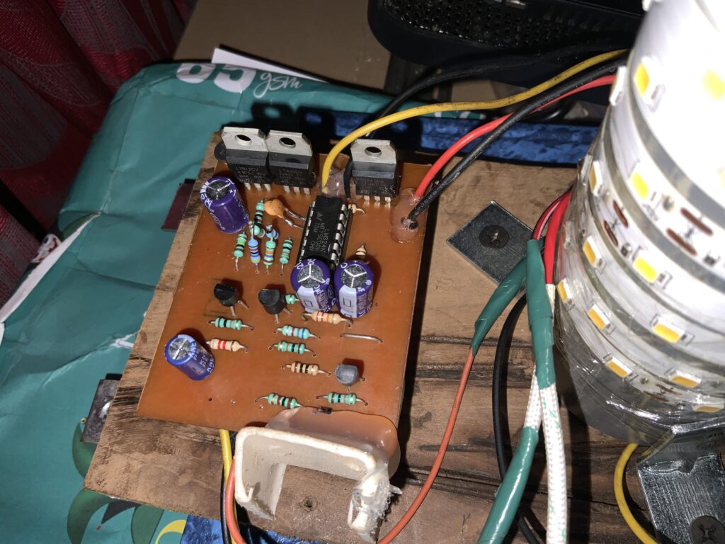
PCB Layout


Nice project thanks for the idea 💡
You are welcome