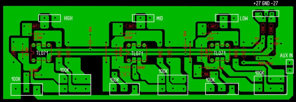
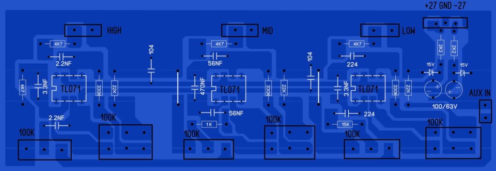
In this post, I’m going to share some interesting electronic circuits for a 3-way active cross-over PCB Layout. The complete project files can be downloaded. The download link is at the bottom of this article. The circuit is designed with a TL071 op-amp IC. The active cross-over board can separate the audio signals according to their nature.
The output will be High frequency, especially for the tweeter to work. The next is mid-frequency, which is most important for Human vocal clarity in the home audio system. The Third is the Low-frequency cross-over section. From this output stage, only low audio signals will be delivered.
What is a 3-way crossover?
The 3-way crossover, from the name itself, mentions the meaning of a 3-way passage of different types of audio frequency. The audio coming from the audio system is in mixed form of audio frequency, The 3-way crossover helps to separate this frequency and pass through the 3 different audio amplifiers for more clarity and performances
The three-way crossover is constructed as a combined circuit of high-frequency, Mid-frequency, or Bandpass filters and low-pass filters, which are denoted as HPF, BPF, and LPF, respectively. Each filter has its own efficiency and working performance in the audio system.
Difference between Active crossover and Passive crossover
The crossover is in two types, Active crossover and Passive crossover. These two type of crossover is working based on different ways. The passive crossover didn’t need any external power supply. The active filter needs an external power supply.
passive crossover is connected at the output stage of the amplifier which may reduce the performance of the amplifier. The active crossover connects to the pre-section of the amplifier audio amplifier input, so there is no power loss of the amplifier.
Check how i build 2-way Passive Crossover circuit for center channel
3 Way active crossover PCB Layout
