This Low pass filter circuit is working Based on the op-amp ic NE5532. It is a dual op-amp integrated circuit. which will provide a high-quality audio signal. So in this article, I’m going to share some ideas about the circuit and its PCB.
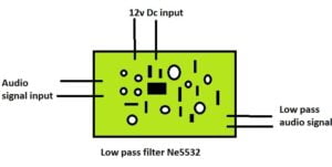
The basic principle of the subwoofer filter is very simple. and the sound of the subwoofer filter is awesome, we can feel the audio sounds.
What is low-pass filter
The normal listening audio signal ranges from 20hz to 2khz. This signal includes bass, treble, and noise of the audio. However, the subwoofer works with a specific frequency range from 20hz to 150hz. For this, we need a device to filter the audio frequency.
The subwoofer filter will allow the low range of audio signals such as 20hz to 2khz. Blocks the high audio signals from 500Hz to 2KHz. This is called a low-pass filter.
NE5532 low pass filter circuit
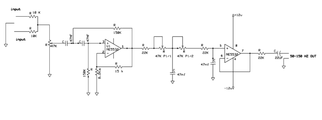
Working of the circuit
The subwoofer filter circuit is working based on the IC NE5532. The 47k preset pot will allow you to control and adjust the frequency of the audio.
It will control the frequency from 50hz to 150hz. with a few few components, you can build this circuit. The power supply provides a 12v dual power supply as 12-0-12 v dc.
Components required
- NE5532 ic – 1
- 47k liner pot – 1
- 10k – 2
- 47k preset pot – 1
- 47nf capacitor – 4
- 150k resistor – 2
- 8.2k resistor – 1
- 15 k resistor – 1
- 22k resistor – 3
- 22uf capacitor – 1
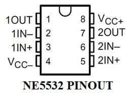
NE5532 ic pinout
Power supply circuit for Filter board
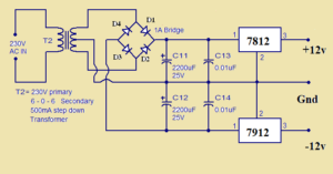
- Use a 12-0-12 center-tapped transformer for this power supply circuit.
- use 1N4007 diode is a 1 A diode.
- check all the connections after soldering.
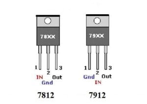
7812 and 7819 regulator ic pinout
You may also check other low-pass filter circuits here
know about Butterworth filter in detailed


