The Project is based on the IR Sensors and A common IC of CD 4017. The circuit will work when the IR signals are detected. The connected relay circuit will turn on and then the connected home appliances will be turned on. So build Your own IR sensor remote control circuit at home with our guidance.
- Also, check ARDUINO BASED REMOTE CONTROL CIRCUIT & CODE
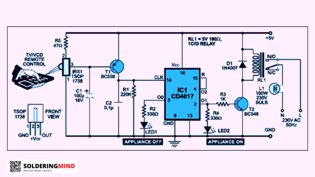
Circuit Diagram
Working
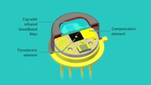
In most home appliances infrared sensors are used to turn on/off the TV or VCD, DVD, etc.. The 38KHz generated by the remote is led and it has to be received through the IR receivers. TSOP 1738 the IR receiver the first pin connected to the ground.
2nd pin is connected to the positive voltage side using a 47R resistor and the 3rd pin is the signal output pin, which carries the output signal to the input clock pin of the CD4017 IC.
The getting signals are weak so a transistor is connected with the receiver’s 3rd pin and the signals get boosted. The amplified signals from BC548 will be fed to the clock pin of 14th in CD4017 ic.
The output will be taken from the IC1 pin 2, and it has to be connected to the transistor’s base pin to drive the relay circuit. A normal 5V 10a relay is used for switching applications.