Wireless water level indicator is one of the essential electronic device needed in busy life. This circuit reminds you about the water level inside the water tank. Lets build your own wireless water indicator using this simple circuit.
Introduction to Wireless water level indicator
A wireless water level indicator is a device that helps measure the level of water in a tank or reservoir and sends this information wirelessly to a display or receiver.
The indicator has a few parts, including a sensor that detects the water level, a transmitter that sends the data wirelessly, and a display unit that receives and shows the data ( Glowing led ).
Different types of sensors are used to measure water levels, such as ultrasonic, pressure, and capacitive sensors.
Ultrasonic sensors use sound waves, pressure sensors measure the pressure of the water, and capacitive sensors measure changes in a capacitor’s capacitance.
In this water level indicator project we are using 434MHz Rf transmitter and receiver. Which will allow the transfer of data wirelessly.
RF module 434mhz for Water level indication
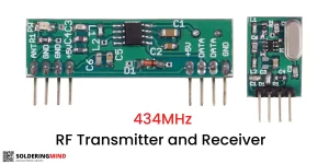
A 434 MHz RF transmitter is a device that can send radio frequency signals at a specific frequency of 434 MHz.
It is typically used in wireless communication systems that require remote control applications, such as electronic toys, garage door openers, and wireless doorbells.
The transmitter usually consists of a few different parts, including an oscillator, a modulation circuit, an amplifier, and an antenna.
The oscillator generates the carrier frequency, which is then modulated with the signal to be transmitted. The amplifier increases the power of the signal, and the antenna sends the signal out into the air.
The Receiver which receive the signal and turn on the output devices connected with the RF receiver.
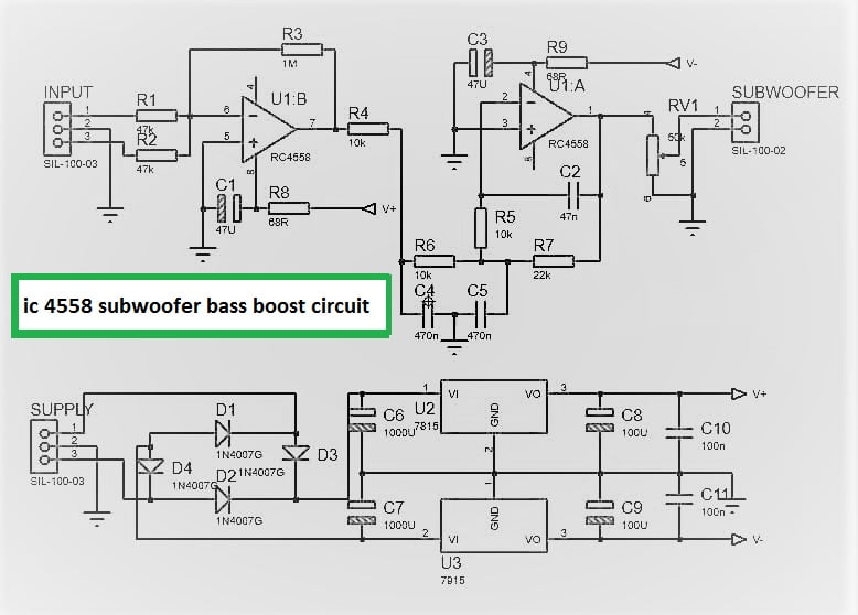
Wireless water level indicator circuit diagram
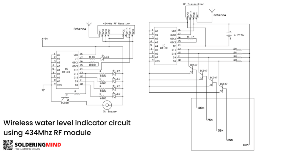
The circuit diagram is contains HT 12D and HT 12E IC and 434MHz rf module. Those are both send and receive signals. Then it works based on the signals receiving from the transmitter.
The HT 12D and HT 12E ICs, when used with a 434 MHz RF module, are commonly used for wireless communication applications. These ICs are encoder and decoder chips that enable data transmission and reception wirelessly over short distances.
The HT 12E encoder IC takes on the role of encoding the data to be transmitted, while the HT 12D decoder IC decodes the received data. The 434 MHz RF module is used to send and receive the encoded and decoded data wirelessly.
The HT 12E encoder IC can be linked to a microcontroller or other device that generates the data to be transmitted. The encoder converts the data into a stream of bits in serial format, and this data is then modulated onto the carrier frequency of the 434 MHz RF module. The encoded data is then transmitted wirelessly.
On the receiving end, the HT 12D decoder IC is linked to a microcontroller or other device that receives the encoded data. The decoder converts the received data into the original data format and sends it to the microcontroller for further processing.
Working
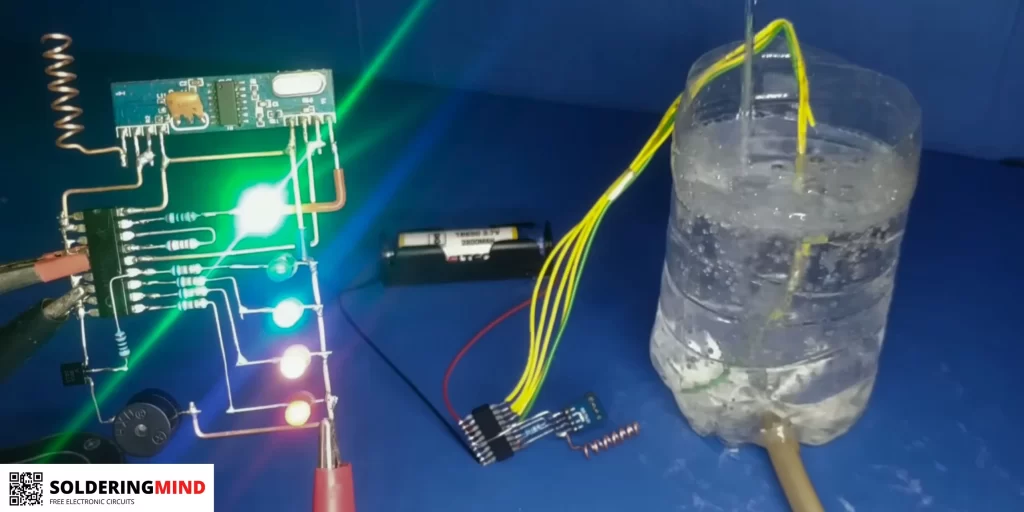
The IC HT 12E PIN number 13, 12, 11 and 10 are sensing the water level in different height on the tank. When water comes contact with these pins and ground will activate the IC.
After that it send a signal to the receiver by 434MHz rf transmitter. At the Receiver receive the data and activating the pins as per it received. The tank has less water the first LED will grow.
In the time of water overflowing the top LED will glow and produce the warning sign of buzzer sound.
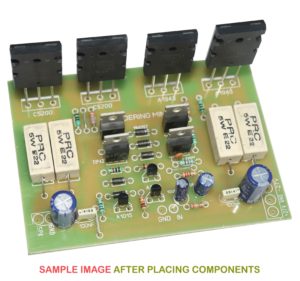
Wireless Water Level Indicator PCB Layout
- Download Wireless water level indicator Receiver PCB layout
- Download Wireless water level indicator Transmitter PCB Layout
Conclusion
In conclusion, a water level indicator that utilizes a 434MHz RF module is a straightforward and useful way to remotely monitor the water level in a tank or other container.
This type of system consists of a water level sensor that is positioned inside the tank to measure the water level and a 434MHz RF module that wirelessly transmits the sensor data to a receiver unit.
The receiver unit can be located within the range of the transmitter and provides an easily readable display of the water level information.
This type of system can be particularly useful in a range of contexts, including industrial settings, agricultural applications, and home automation systems.
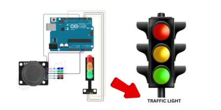
Related Projects
📌 Automatic Water Tank filling Circuit

Kya kit aap de skate hai
Nice video you made, complete with pcb artwork. The circuit works like a charm. Well done!
Thanks buddy
Sir i need free energy device 220 volt 5kva design
I don’t understand can you please explain it briefly