The automatic water tank filling system is a simple project designed by a timer IC 555. The time has to be adjusted in the circuit after the specified time in the circuit the pump will go to of state and stop filling water.
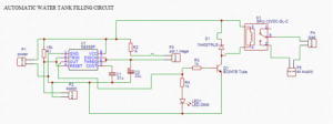
The automatic water filling system circuit diagram and the free PCB layout is given in this website and my YouTube channel. Download and do it yourself.
Working of automatic water tank filling project
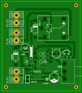
The circuit is constructed on a printed circuit board and the connections are properly done with soldering iron and lead.
The time has to be adjusted by the capacitor and the Potentiometer connected in the circuit. Any changes have to be made on the values of the capacitor and the resistor will change the time duration of the circuit.
The time of filling water is varies according to the storage capacity of the water tank. Example the 2000 liter water tank needs 10 minutes to fill up. And the 4000-liter water tank needs 15 minutes to fillup.
So adjust the Potentiometer to your convenient time. After the Specified time, the relay get on or off this can control the motor pump
Water tank automatic system circuit
Working of this circuit
The circuit is working based on the delay on of the relay. When we set a particular time to on the relay the relay will be turned on and disconnect the relay from the ac contact.
The ac connected with the relay input pin and an output pin the water pumping motor has to be connected.
so the circuit is on the water pump gets on and off when the tank is fully filled with water at a particular time period.
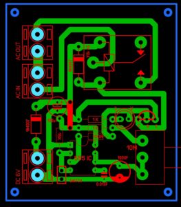
Automatic water tank PCB layout
Download PCB layout
NOTE: you can increase the delay of the relay on time by increasing the values of the capacitor (100uf) and 10M potentiometer. I set this circuit up to 16min time delay. if you want to increase the time delay comment to this post.


200 watt inverter PCB kitne ki milegi