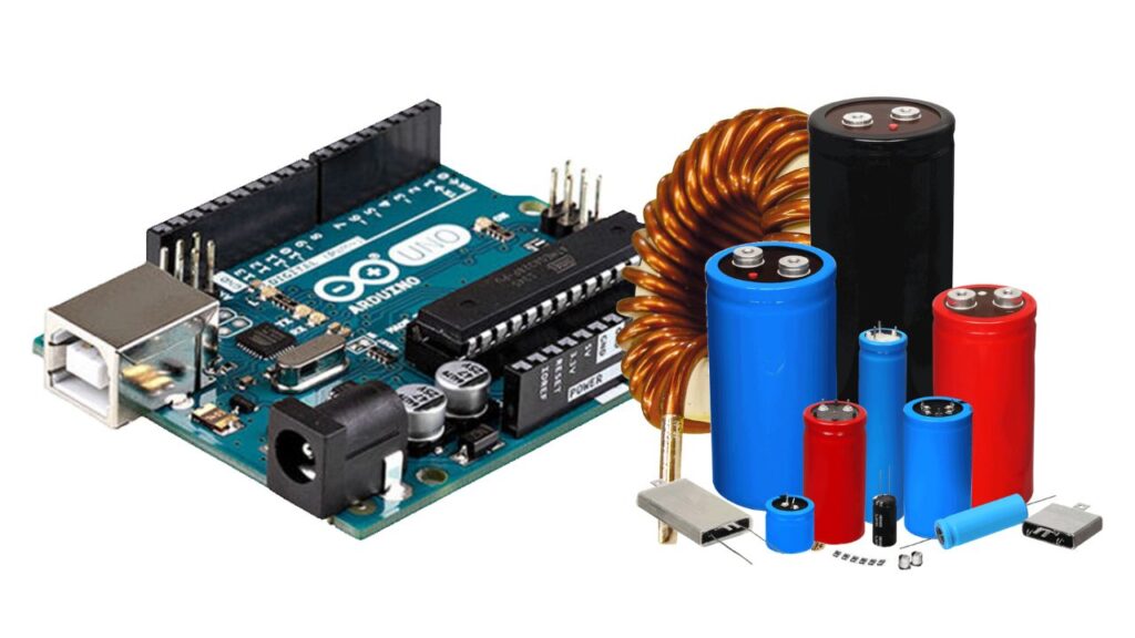
An LC (inductance and capacitance) meter is a device that measures the inductance and capacitance of a circuit. An Arduino microcontroller ( ATMEGA328P ) can be used to build an LC meter, by using the Arduino’s analog-to-digital converter (ADC) to measure the voltage across a known current flowing through the circuit.

Also Check: Arduino Based Electronics Projects
Here is an example of Arduino code for an LC meter:
#include <LiquidCrystal.h>

int sensorPin = A0; // select the input pin for the sensor
int ledPin = 13; // select the pin for the LED
int sensorValue = 0; // variable to store the value coming from the sensor
float frequency = 0;
unsigned long time = 0;

LiquidCrystal lcd(7, 6, 5, 4, 3, 2);

void setup() {
  pinMode(ledPin, OUTPUT);
  lcd.begin(16, 2);
  lcd.print("LC Meter");
  delay(1000);
}

void loop() {
  // read the value from the sensor:
  sensorValue = analogRead(sensorPin);
  // convert the analog reading (which goes from 0 - 1023) to a voltage (0 - 5V):
  float voltage = sensorValue * (5.0 / 1023.0);
  // calculate the frequency using the voltage and a known current:
  frequency = (1 / (2 * 3.14159265359)) * (voltage / 0.00001);
  // turn on the LED:
  digitalWrite(ledPin, HIGH);
  // measure the time for one half-cycle:
  time = micros();
  while (digitalRead(sensorPin) == HIGH) {}
  time = micros() - time;
  // turn off the LED:
  digitalWrite(ledPin, LOW);
  // display the frequency and time on the LCD:
  lcd.clear();
  lcd.print("Frequency: ");
  lcd.print(frequency);
  lcd.print(" Hz");
  lcd.setCursor(0, 1);
  lcd.print("Time: ");
  lcd.print(time);
  lcd.print(" us");
  delay(1000);
}
This code uses the Arduino’s analog-to-digital converter (ADC) to measure the voltage across a known current flowing through the circuit. Then, it uses the voltage and known current to calculate the frequency of the signal.
It also uses the Arduino’s micros() function to measure the time for one half-cycle of the signal, which can be used to calculate the inductance or capacitance. The resulting frequency and time measurements are then displayed on an attached LCD screen.
It’s worth noting that this is a simple example, the code could be improved in many ways, for example, by adding some error handling, displaying the units of the measurements and adding a menu to switch between measuring inductance and capacitance.
Also, the code was written assuming that the circuit to be measured is connected to the analog pin A0, and an LED is connected to the digital pin 13, if that is not the case, you should change the pin numbers accordingly.
- TDA2030 Pinout, Specification and Working
- CD4047 Multivibrator IC: Pinout, Function and Equivalent
- 1.5v LED Driver Circuit for Mini Flashlight
- 1000 W Driver Amplifier
- Class H Audio Amplifier


