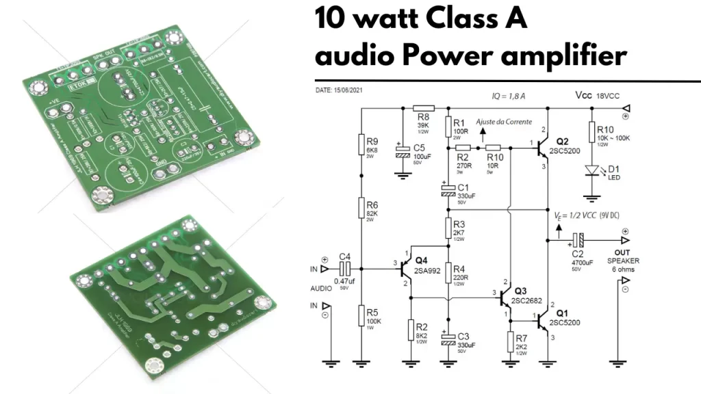
Are you looking for the best class amplifier circuit? Lot of electronics websites don’t have the perfect solution for that. So I decided to share the 10 watt Class A Audio Power Amplifier circuit diagram and its complete details here. Additional gift is the PCB.
Class A audio power amplifier
The class a audio power amplifier is the best audio amplifier designed for better audio quality and smooth experience. The circuit of it characterized by the output transistor is conducting every time. The same copy of the input signal wave is amplified by this class of amplifiers.
Amplifier Circuit Diagram
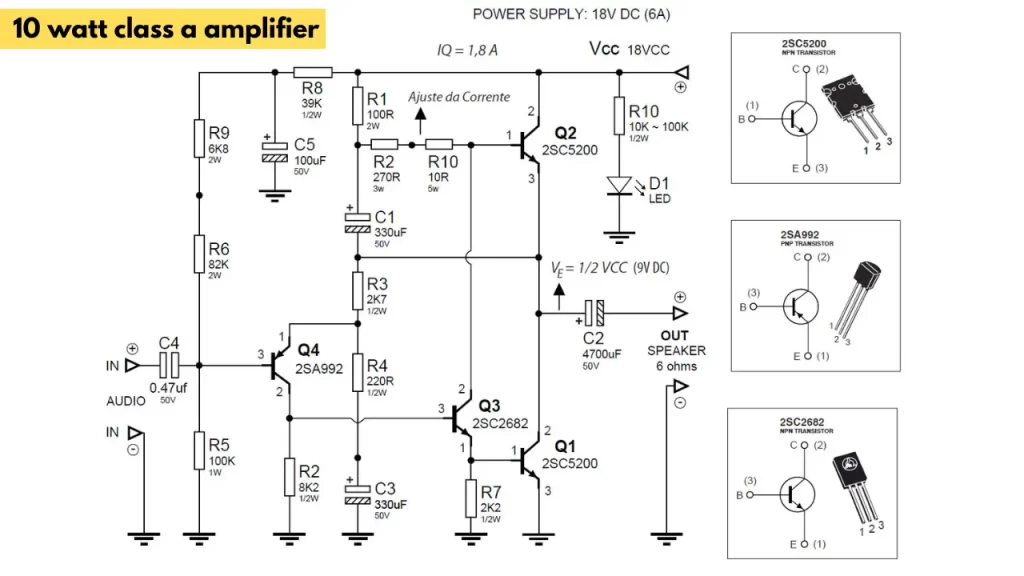
You can replace the 2SC5200 transistor with a 2N3055 metallic package transistor or TIP3055 Plastic package transistor. Both transistors work well. Use a big aluminum heatsink to cool down the amplifier when working. so don’t forget to attach a good quality heatsink with the transistor.
Power supply circuit
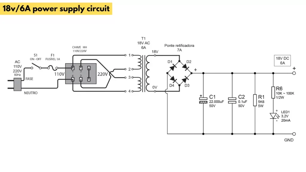
The power supply for the amplifier is recommended to use 18v at 6A. You can use any normal AC to DC 18v/6A transformer to get continuous 18v at the output. Use good quality diodes and capacitors for rectification. I recommended using a metallic 35A bridge rectifier.
Class A amplifier Power stage

High quality NPN transistors are used for the output section. in the circuit diagram the 2SC5200 is using, you can also use this TIP3055. The 2sc5200 can carry more current through the transistor and the heat dissipation area is wide so the transistor gets cool faster.
Working of Class A amplifier
The output transistor is biased, so the transistor will always conduct current. This will happen without any input signal also. This will make the transistor very hot. The continuous power dissipation through the power transistor makes it very hot at the heatsink or near its area.
JLH1969 10 watt Class A amplifier PCB

🎁 Also check other audio amplifier circuits

