The single ended Class A Amplifier is a type of amplifier, where the only single active output component doing the work. The passive part can handle the load at the output section like Resistor, Inductor or transformer.
Some fancy designs of inductor or transformer can negatively affect the performance of the amplifier sound. Because they lose the frequency at different ranges.
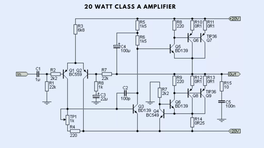
This amplifier is based on the circuit of a 60 watt power amplifier. But the circuit is modified for the true Class A amplifier operation. So the amplifier circuit is generally considering high quality sound output.
Many people have been building this project and most of them are talking positively about this project.
Circuit
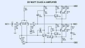
When using a power supply of (20V dual power supply) the amplifier produces 22 watts of power output. You must take care of the usage of large heatsink to the transistors because of the large amount of heat that can be produced through the power stage.
Using below 3 amps is better for its working. High current may damage the transistor and also the driver stage of the amplifier.
Using MJE2955 instead of the current transistors
MJE2955 will be quite hot and the temperature ranges from 65-70 degree Celsius. When it exceeds their safe power limit of 45 watt. So you must use two of these transistors. So using two transistors each transistor dissipating 27.5 watt of heat and this will also help for heat transferring to the heat sink.
I strongly recommend using a TO-3 transistor or large plastic case transistor design is good for high heat dissipation. TIP35 and TIP36 are good alternative transistors. It has the higher dissipation level of 125 watts.
The optimum level of Current in the circuit
The best current for the class A amplifier is around 110% of the highest current of your speaker will use. If the speaker have the impedance of 8 ohms and the applied voltage is 22 volt then the maximum speaker current is calculated using
I = V/R = 22/8 = 2.75A
2.6 ampere is quite fine and good to use.

