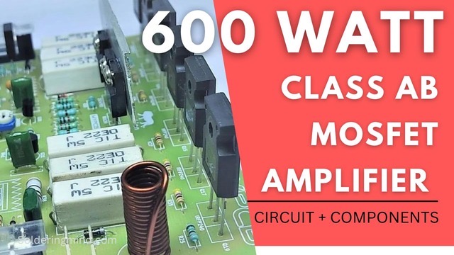
The amplifier can deliver about 600-watt Rms, So let’s check the circuit of the class ab MOSFET amplifier. The circuit diagram and the details of its complete components are given in this article. Three pairs of IRFP9240 P-channel mosfet and IRFP240 N-channel Mosfets are using in the power stage of this amp. The 600 watt amp can able to handle the input voltage upto 55V DC.
Also Check : Subwoofer Low pass filter Board PCB Layout
Features of class ab mosfet amplifier
- Low total harmonic distortion about 0.1%.
- The amplifier works with the input DC voltage of 24v to 55v dual power supply.
- Extra protection is added, the fuse on both rail voltage will protect the board.
- You can use 4 or 8 ohm speakers, wattage rating about 200 to 800 watt.
- The components using in this circuit is very easy to find in local markets.
600 watt Class AB Mosfet amplifier circuit
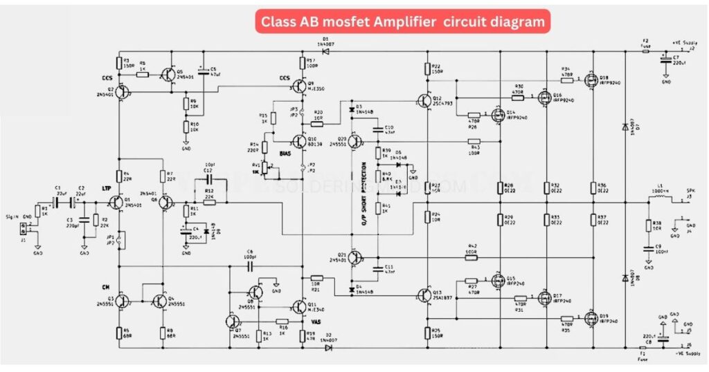
The output stage of this powerful mosfet amplifier is class ab configuration. Each signals coming through the circuit is amplified by the N channel and P channel Mosfets.
IRFP9240 the P channel power mosfet and IRFP240 the N channel power mosfet is well known in audio amplifiers. They provide maximum efficiency of the amplifier circuit in output.
Components list
- IRFP9240 P channel Mosfet.
- IRFP240 N channel mosfet.
- 2N5401 transistor
- 2N5551 Transitor.
- MJE350 & MJE340 Transistor.
- 2sc4793 and 2sa1837 Transistor.
- 1000nH coil.
- 220uf, 22uf, 47uf, electrolytic capacitor.
- 220 pf, 47nf, 100nf, 100pf, capacitor.
- 1K, 22K, 10K, 68R, 22K, 220R, 10R, 47R, 150R, 470R, 6.8K, 0.22R 5WATT, Resistors.
- 1N4148, 1N4007 Diodes.
- 1K preset pot.
- Fuse.
At input stage working as a transconductance amplifier. The stage contains Q1 working as a differential amplifier. The input signal is amplified by the Q1 transistor and then it sends to vas from collector.