A 12V battery charger circuit is a device that converts an external power source, such as a AC mains or a DC source, into a DC voltage that can be used to charge a 12V lead-acid battery. There are a variety of different circuit designs that can be used to accomplish this task, but some of the most common include the following:
- Linear charger: A linear charger uses a transformer to step down the incoming voltage, and then a linear regulator, typically a series pass transistor, to convert the high voltage, high current AC into a steady DC voltage to charge the battery.
- Switch mode charger: A switch mode charger uses a switching power supply to convert the incoming voltage into a high frequency AC voltage, which is then converted back into a DC voltage using a rectifier and filter circuit. These type of charger are more efficient than linear chargers, but they generate more heat and can be more complex to design.
- Microcontroller-based charger: A microcontroller-based charger uses a microcontroller to control the charging process and provide features such as over-voltage protection, short-circuit protection, and temperature monitoring. They tend to be more accurate and flexible than linear or switch mode chargers.
Regardless of the design, a proper circuit need to have protection such as thermal and over current protection to prevent damage to the charger or the battery. It is also important to note that not all 12V batteries are the same, and some may require specific charging algorithms, so it is important to match the charger with the specific battery type and manufacturer’s specifications.
Linear Battery Charger Circuit
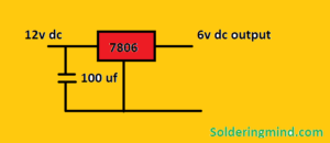
A 12V DC linear charger is a type of battery charger that uses a linear regulator to convert a high voltage, high current AC or DC input into a steady DC voltage that can be used to charge a 12V lead-acid battery.
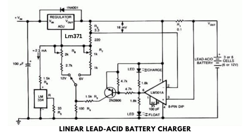
The basic circuit of a 12V DC linear charger typically consists of a transformer to step down the incoming voltage, a rectifier to convert the AC voltage into DC, and a linear regulator to provide a stable output voltage.
The transformer is the first stage of the circuit, it steps down the AC voltage to a lower voltage that is appropriate for charging the battery. The rectifier converts the AC voltage into DC voltage and filters it so that the output is smooth.
The linear regulator is the key component of the circuit, it uses a series pass transistor to regulate the output voltage and current flowing to the battery. By adjusting the voltage on the base of the transistor, the output voltage can be adjusted to match the voltage required to charge the battery.
The last stage of the circuit is protection, which can include a fuse or circuit breaker, to protect the circuit from damage due to high currents and short circuits. Thermal protection can also be added to protect the linear regulator from overheating.
It is important to note that not all 12V batteries are the same and may require specific charging algorithms, so it is important to match the charger with the specific battery type and manufacturer’s specifications. Also, the linear charger can generate heat and can be less efficient than other types of chargers.
Switch Mode Battery Charger
A 12V lead-acid switch mode charger is a type of battery charger that uses a switching power supply to convert an incoming AC or DC voltage into a high frequency AC voltage, which is then converted back into a DC voltage using a rectifier and filter circuit.
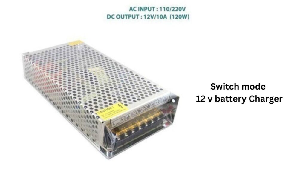
The advantage of switch-mode power supplies is that they are generally more efficient and compact than linear power supplies, which makes them well-suited for battery charging applications.
The basic circuit of a 12V lead-acid switch mode charger typically consists of a rectifier to convert the AC voltage into DC, a switching converter to convert the DC voltage into a high-frequency AC voltage, and a filter circuit to convert the high-frequency AC voltage back into a DC voltage that can be used to charge the battery.
The rectifier is the first stage of the circuit, it converts the incoming AC voltage into DC voltage.
The switching converter is the key component of the circuit, it converts the DC voltage into a high-frequency AC voltage and regulates the voltage output. It can also help in adjusting the charging current based on the battery charge status.
The filter circuit is the last stage of the circuit, it converts the high-frequency AC voltage back into a DC voltage and filters it so that the output is smooth and stable.
The circuit also includes protection features such as over-voltage protection, short-circuit protection, and temperature monitoring, that protect the charger and the battery from overcharge, overcurrent, and high temperature.
It is important to note that not all 12V lead-acid batteries are the same, and some may require specific charging algorithms, so it is important to match the charger with the specific battery type and manufacturer’s specifications.
Microcontroller based Charger
A microcontroller-based 12V lead-acid battery charger is a type of battery charger that uses a microcontroller to control and monitor the charging process. This type of charger uses an external power source, such as an AC main or a DC source, to convert into a DC voltage that can be used to charge a 12V lead-acid battery.
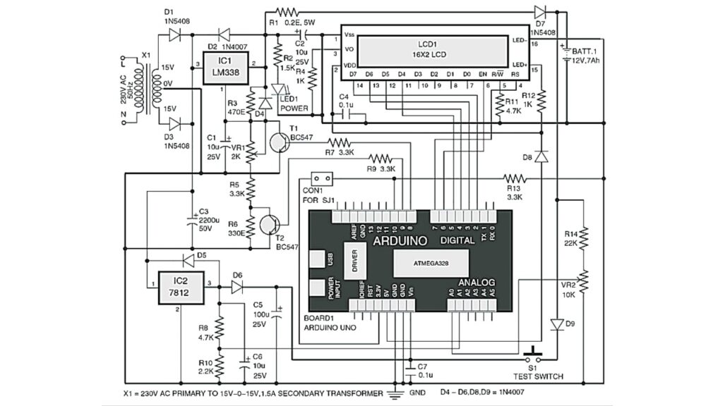
The basic circuit of a microcontroller-based 12V lead-acid battery charger typically consists of a rectifier to convert the AC voltage into DC, a switching converter to convert the DC voltage into a regulated DC voltage, a microcontroller to control and monitor the charging process, and a protection circuit to protect the charger and the battery from overcharge, overcurrent and high temperature.
The rectifier is the first stage of the circuit, it converts the incoming AC voltage into DC voltage.
The switching converter is the second stage of the circuit, it converts the DC voltage into a regulated DC voltage that matches the voltage required to charge the battery.
The microcontroller is the key component of the circuit, it controls the charging process by adjusting the charging current based on the battery charge status and also provides features such as over-voltage protection, short-circuit protection, temperature monitoring, and charge status indication.
The protection circuit is the last stage of the circuit, it protects the charger and the battery from overcharge, overcurrent, and high temperature by using a fuse, a circuit breaker, or thermal protection.
This type of charger can be designed to implement specific charging algorithms that are appropriate for the specific type of lead-acid battery, for example, a two-stage charging algorithm or temperature compensation. They are more accurate and flexible than linear or switch-mode chargers, but they tend to be more complex to design.
Source Code for Microcontroller-based 12v Battery Charger Circuit
#include <LiquidCrystal.h>

//               RS  E  D4 D5  D6 D7
LiquidCrystal lcd(7, 6, 5, 4, 3, 2);

int ADC_PIN = A0;
int PWR_PIN = A1;
int CHRG_OFF_PIN = 8;
int CHRG_LOW_PIN = 9;
int CALIBRATION_PIN = 10;
int LED_IND  = 13;
int ADC_VAL = 0;
int PWR_VAL = 0;
int VOLTS = 0;
int isCalibrate=0;
int loopno=0;

void setup()
{
  pinMode(LED_IND, OUTPUT);
  pinMode(CHRG_OFF_PIN, OUTPUT);
  pinMode(CHRG_LOW_PIN, OUTPUT);
  pinMode(CALIBRATION_PIN, INPUT);
  digitalWrite(CHRG_OFF_PIN, HIGH);
  digitalWrite(CHRG_LOW_PIN, HIGH);
  delay(2000);
  lcd.begin(16, 2);
  lcd.setCursor(0, 0);
  lcd.print ("Arduino controld" );
  lcd.setCursor(0, 1);
  lcd.print("12V battery chrgr");
  delay(1000);
  lcd.clear();
}

void loop()
{
  START:
  loopno++;
  isCalibrate = digitalRead ( CALIBRATION_PIN );
  digitalWrite(LED_IND, HIGH);
  if ( isCalibrate == HIGH )
  {
    digitalWrite(CHRG_OFF_PIN, LOW);
    digitalWrite(CHRG_LOW_PIN, LOW);
  }
  else
  {
    digitalWrite(CHRG_OFF_PIN, HIGH);
    digitalWrite(CHRG_LOW_PIN, HIGH);
  }
  delay(20);
  PWR_VAL = analogRead (PWR_PIN);
  delay(20);
  ADC_VAL = analogRead(ADC_PIN);
  VOLTS = (ADC_VAL+2) / 4;

  lcd.setCursor(0, 0);  lcd.print (VOLTS/10);   lcd.print (".");   lcd.print (VOLTS%10);   lcd.print (" V   ");

  if ( isCalibrate == HIGH )
  {
    lcd.setCursor(0, 1);  //lcd.print ("STATUS:" );
    lcd.print ("CALIBRATION.....");
    lcd.setCursor(7, 0);  lcd.print ("A0 = " );   lcd.print (ADC_VAL); lcd.print ( "   " );
    delay(500);
    goto START;
  }

  if ( VOLTS>130 )
  {
    digitalWrite(CHRG_OFF_PIN, LOW);   digitalWrite(CHRG_LOW_PIN, HIGH);
    lcd.setCursor(7, 0); lcd.print ("CHRG.FULL" );
    lcd.setCursor(0,1);  if(PWR_VAL<600) lcd.print( " CHARGER IS OFF " ); else lcd.print ("FLOAT CHARGING. " );
  }
  else if ( VOLTS<=15 )
  {
    digitalWrite(CHRG_OFF_PIN, HIGH);   digitalWrite(CHRG_LOW_PIN, HIGH);
    lcd.setCursor(7, 0); lcd.print ("NO BATTRY" );
    lcd.setCursor(0,1);   if(PWR_VAL<600) lcd.print( " CHARGER IS OFF " ); else  lcd.print ("  NOT CHARGING. " );
  }
 else if ( VOLTS<80 )
  {
    lcd.setCursor(7, 0); lcd.print ("BATT:DEAD" );
    lcd.setCursor(0,1);   if(PWR_VAL<600) lcd.print( " CHARGER IS OFF " ); else  lcd.print (" SLOW CHARGING. " );
    delay(1000);
    digitalWrite(CHRG_OFF_PIN, LOW);   digitalWrite(CHRG_LOW_PIN, HIGH);
  }
  else if ( VOLTS<110 )
  {
    digitalWrite(CHRG_OFF_PIN, LOW);   digitalWrite(CHRG_LOW_PIN, LOW);
    lcd.setCursor(7, 0); lcd.print ("BATT:WEAK" );
    lcd.setCursor(0,1);    if(PWR_VAL<600) lcd.print( " CHARGER IS OFF " ); else  lcd.print (" FAST CHARGING. " );
  }
  else
  {
    digitalWrite(CHRG_OFF_PIN, LOW);   digitalWrite(CHRG_LOW_PIN, LOW);
    lcd.setCursor(7, 0); lcd.print ("BATT:GOOD" );
    lcd.setCursor(0,1);   if(PWR_VAL<600) lcd.print( " CHARGER IS OFF " ); else  lcd.print (" FAST CHARGING. " );
  }


  if ( loopno%2 )
  {
    lcd.setCursor(15,1);
    lcd.print ( '.' );
  }

  if(loopno>1000)
    loopno = 0;
  digitalWrite(LED_IND, LOW);
  delay(2000);
}
Conclusion
A linear charger, switch mode charger, and microcontroller-based charger are all types of battery chargers that can be used to charge a 12V lead-acid battery.
A linear charger uses a linear regulator to convert a high voltage, high current AC or DC input into a steady DC voltage that can be used to charge the battery. Linear chargers are simple and less expensive to build, but are less efficient and generate more heat compared to switch mode chargers.
A switch mode charger uses a switching power supply to convert an incoming AC or DC voltage into a high-frequency AC voltage, which is then converted back into a DC voltage using a rectifier and filter circuit. Switch mode chargers are more efficient than linear chargers and generate less heat, but they tend to be more complex to design.
A microcontroller-based charger uses a microcontroller to control and monitor the charging process and provides features such as over-voltage protection, short-circuit protection, temperature monitoring, and charge status indication. These chargers tend to be more accurate and flexible than linear or switch-mode chargers but are also more complex to design.
In summary, each type of charger has its own set of advantages and disadvantages, and the choice of which type to use will depend on the specific requirements of the application, such as efficiency, size, cost, and required features.