In this article i’m going to share the circuit diagram and explanations about Pir Motion Sensor based Relay On/Off project. The PIR sensor is also known as a Passive Infrared Sensor is an electronic sensor will detects the motion using infrared radiations emitted by the hot bodies or objects. That measures infrared light radiated from objects in the field of you they are most often used in PCR based motion detector.
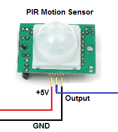
PIR Montion Sensor
How Does a PIR Motion Sensor Works?
when the sensor is ideal both slots detect the same amount of IR. The ambient amount radiated from the room. when a warm body like a human or animal passed, by its first intercepts one half of the IR sensor which cause a positive differential change between the two halves.
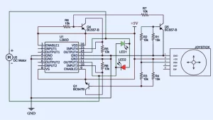
PIR Motion Sensor Relay Circuit

Working of This Circuit
When the Pir sensor connected with the circuit. the circuit will be connected by a battery then the infrared radiation will be produced by the motion sensor. When an object that intersects the infrared radiation it will produce a positive signal output in the output pin of the sensor. Then the positive output pin will be biased with a transistor and it will open the transistor and work the relay this is the common working principle of the circuit.
Assembling of motion sensor
Use soldering dot prototype board like the one show about to assemble and solder the components. and make your own PCB using the schematic given below first solder 7805 voltage regulator to the board. Next soldering 9-volt battery connected wires to the pins on the voltage regulator as shown in the schematic.
Define the unit for the PIR motion sensor to get the picture at the top of the page or check for marking only Vcc, gnd and the output signal. Connect the PR motion sensors VCC and gnd to the 7805 output.
Then Connect the BC 547 collector to one end of the relay coil. Connect the bass to the PIR motion sensors output signal and the emitter to the ground. Another end of the relay coil is connected to the input voltage 9 volt. connect a 1N14007 diode with its cardboard on the VCC and the animal found the emitter of the BC 547 transistor.
The diode is employed to guard the junction transistor by preventing any reverse voltage from the relay. At last, connect a two-pin screw connector near the relay. The pins of the connector are soldering to the end (NO) which means normally open terminal to the power 5-volt relay. connect two-pin screw connector near the relay. The pins of the connector are soldering to the end (NO) which means normally open terminal to the power 5-volt relay.
Check interesting Hobby electronic circuit


would like to be a membe
r in research on electronic/electrical projects
contact me [email protected]