Build a Knight rider LED Chaser circuit using ATtiny 85 Programmable IC. This simple and compact circuit works with upto 80 LED’s. Lets Build one.
What is Knight Rider
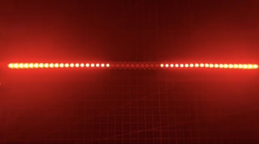
A Knight Rider LED chaser, also known as a KITT scanner. This is an electronic circuit that controls the sequence of multiple LEDs to create a visual effect.
The circuit usually consists of a microcontroller ( ATtiny85 ), a series of LEDs, and supporting components such as resistors and capacitors.
The microcontroller controls the timing and sequence of the LED lights, which are arranged in a specific pattern to achieve the desired effect.
There are many different ways to design a Knight Rider LED chaser circuit, and the level of complexity can vary depending on the desired effect.
Some circuits use simple timing circuits, while others use more advanced microcontrollers with built-in LED driver circuits.
Building a Knight Rider LED chaser can be a fun and challenging project for electronics enthusiasts, but it’s important to exercise caution when working with electrical components.
Always follow proper safety procedures and use caution when working with live circuits to avoid injury or damage to equipment.
Knight Rider Led Chaser Circuit Diagram
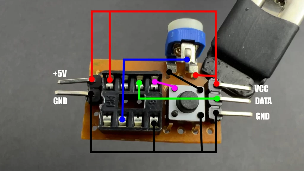
Programming Code
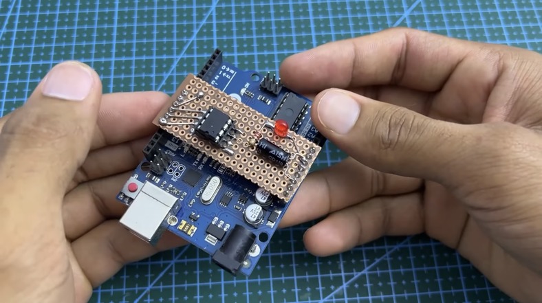
You need to upload the given code to your Attiny85 Microcontroller to work. So you can use normal arduino board to upload the sketch. If you are not sure about how to upload the code Check this tutorial : ATtiny85 IC Programming Using Arduino
#include "Arduino.h"
#include <FastLED.h>
#define LED_PIN 1     //LED Strip Signal Connection
#define VR_PIN 3      //Potentiometer / Preset Pin for Speed Adjusting
#define buttonPin 0   //Push Button Pin

#define NUM_LEDS 60   //Total no of LEDs in the LED strip. You can safely go upto 80 LEDs.

CRGB leds[NUM_LEDS];

int r, g, b;
int ColourTrig;
int LEDPower = 0;
int numb=1;
int pres=0;
int VR_SPEED;
int SPEED;

void setup()
{
FastLED.addLeds<WS2812, LED_PIN, GRB>(leds, NUM_LEDS);
FastLED.clear();
pinMode(buttonPin, INPUT_PULLUP);
}

void loop()
{
VR_SPEED = analogRead(VR_PIN);
SPEED = map(VR_SPEED, 0, 1023, 15, 30);

ButtonScan();

switch (numb) {
  case 1:
    Pattern1(1); //You can change LED colour in "X", Pattern1(X) X = 1-Red, 2-Magenta, 3-Blue, 4-Cyan, 5-Green, 6-Yellow, 7- White
    break;
  case 2:
    Pattern1(2);
    break;
  case 3:
    Pattern1(3);
    break;
  case 4:
    Pattern1(4);
    break;
  case 5:
    Pattern1(5);
    break;
  case 6:
    Pattern1(6);
    break;
  case 7:
    Pattern1(7);
    break;
  case 8:
    Pattern2(1);
    break;
  case 9:
    Pattern2(2);
    break;
  case 10:
    Pattern2(3);
    break;
  case 11:
    Pattern2(4);
    break;
  case 12:
    Pattern2(5);
    break;
  case 13:
    Pattern2(6);
    break;
  case 14:
    Pattern2(7);
    break;
  case 15:
    Pattern3(1);
    break;
  case 16:
    Pattern3(2);
    break;
  case 17:
    Pattern3(3);
    break;
  case 18:
    Pattern3(4);
    break;
  case 19:
    Pattern3(5);
    break;
  case 20:
    Pattern3(6);
    break;
  case 21:
    Pattern3(7);
    break;
  default:
    break;
}
}

void Pattern3(int ColourTrig)
{
switch (ColourTrig)
 {
  case 1:
  r = 255;
  g = b = 0;
  break;

  case 2:
  r = b = 255;
  g = 0;
  break;

  case 3:
  b = 255;
  r = g = 0;
  break;

  case 4:
  b = g = 255;
  r = 0;
  break;

  case 5:
  g = 255;
  r = b = 0;
  break;

  case 6:
  r = g = 255;
  b = 0;
  break;

  case 7:
  r = g = b = 255;
  break;
}

  for (int i = 0; i < (NUM_LEDS/2); i++)
  {
  leds[(NUM_LEDS/2)+i] = CRGB(r, g, b);
  leds[((NUM_LEDS/2)-1)-i] = CRGB(r, g, b);
  FastLED.show();ButtonScan();
  delay (SPEED);
  }
  for (int i = 0; i < (NUM_LEDS/2); i++)
  {
  leds[(NUM_LEDS/2)+i] = CRGB(0, 0, 0);
  leds[((NUM_LEDS/2)-1)-i] = CRGB(0, 0, 0);
  FastLED.show();ButtonScan();
  delay (SPEED);
  }
  delay (200);
}


void Pattern2(int ColourTrig)
{
switch (ColourTrig)
 {
  case 1:
  r = 255;
  g = b = 0;
  break;

  case 2:
  r = b = 255;
  g = 0;
  break;

  case 3:
  b = 255;
  r = g = 0;
  break;

  case 4:
  b = g = 255;
  r = 0;
  break;

  case 5:
  g = 255;
  r = b = 0;
  break;

  case 6:
  r = g = 255;
  b = 0;
  break;

  case 7:
  r = g = b = 255;
  break;
}

fadeToBlackBy(leds, NUM_LEDS, 4);
uint8_t u = beat8(SPEED*1.5, 0);
uint8_t pos1 = map(u, 255, 0, 0, NUM_LEDS);
leds[pos1] = CRGB(r, g, b);
uint8_t pos2 = map(u, 0, 255, 0, NUM_LEDS);
leds[pos2] = CRGB(r, g, b);
FastLED.show();ButtonScan();
}


void Pattern1(int ColourTrig)
{
switch (ColourTrig)
 {
  case 1:
  r = 255;
  g = b = 0;
  break;

  case 2:
  r = b = 255;
  g = 0;
  break;

  case 3:
  b = 255;
  r = g = 0;
  break;

  case 4:
  b = g = 255;
  r = 0;
  break;

  case 5:
  g = 255;
  r = b = 0;
  break;

  case 6:
  r = g = 255;
  b = 0;
  break;

  case 7:
  r = g = b = 255;
  break;
}

fadeToBlackBy(leds, NUM_LEDS, 20);
int pos = beatsin16(SPEED, 0, NUM_LEDS-1);
leds[pos] += CRGB(r, g, b);
FastLED.show();ButtonScan();
FastLED.delay(5);
}


void ButtonScan()
{
if(digitalRead(buttonPin)==0)
   {
    if(pres==0)
   {
    numb++;
    pres=1;
   }
    }
  else
  {
    pres=0;
   }

 if(numb == 22)
 {
 numb = 1;
 }
}
Use
The Knight Rider LED chaser circuit can be used in a variety of applications, including:

- Automotive lighting: The KITT scanner effect can be added to the headlights or tail lights of a car or motorcycle to give it a futuristic look.
- Home lighting: The LED chaser circuit can be used to create interesting lighting effects for parties or other events.
- Signage: The circuit can be used to create animated signs that draw attention to a business or product.
- Art installations: The KITT scanner effect can be incorporated into art installations to create a dynamic visual display.
- Robotics: The circuit can be used to create interesting lighting effects for robots or other electronic projects.


