Introduction
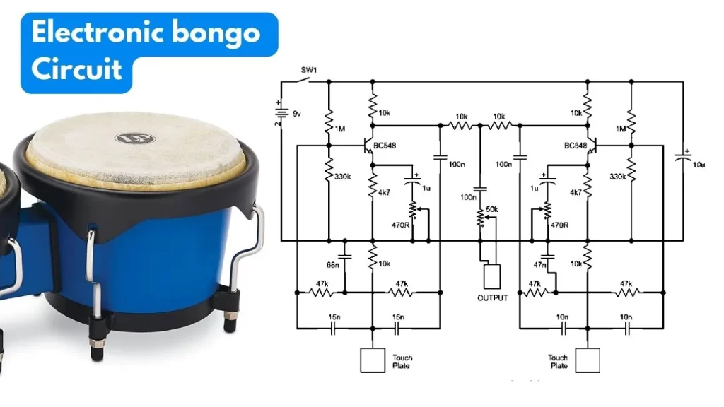
The electronic bongo circuit creates a bongo drum sound when you touch the two sensor plates present on it. You can make the touch plate sensor using any conducting material like copper or aluminum. In this article I would like to share the simple electronic bongo circuit you can build at your home.
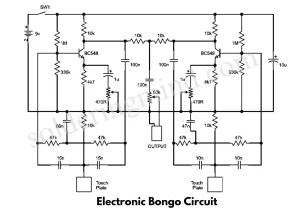
Circuit Diagram
Components Required
| Components | Value | Quantity |
|---|---|---|
| Transistors | BC548, MPSA-18 | 2 |
| Resistor | 10K, 1M, 4K7, 330K, 47K | 6, 2, 2, 2, 4 |
| Variable resistor | 470ohm, 50k ohm | 2, 1 |
| Non polar capacitor | 100nf, 68nf, 47nf, 15nf, 10nf | 2, 1, 1, 2, 2 |
| Electrolytic capacitor | 1uf, 10uf | 2, 1 |
| Battery | 9V | 1 |
| Switch | – | 1 |
Touch Plate for This project
The touch plate is made up of stainless steel, aluminum or copper, Because the touch plate needs to be electricity conducting material. Be aware about not touching each plate at a time.you can fix the touch plate properly and avoid any problems of short circuit.
Use of 470 ohms and 50K Potentiometer uing in This Circuit
The potentiometer RV1 and RV3 are used to set up the bongo circuit. The RV2 controls the sound output level, and the RV3 oscillator section of the circuit.
Working
The electronic bongo circuit comprises two nearly identical twin T-type sine wave oscillators, each dedicated to a touch plate. Each oscillator features a filter within the feedback loop.
If the loop gain surpasses unity, the circuit will oscillate. In this specific use, the gain is fine-tuned to be just slightly below unity. Initiating the oscillator is done by touching the touch plate, but once the finger is removed, oscillations cease. The decay rate is determined by the circuit gain, guided by RV1 and RV3.