Hello friends in this post i am introducing an efficient / Best 12v to 220V Inverter Circuit using Common PWM IC SG3525 / KA3525. The circuit will convert the input 12v dc to high voltage upto 300V DC you can control it by adjusting the feed back preset pot in the circuit diagram.
12v to 220v Inverter Circuit Diagram
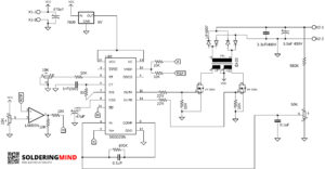
The inverter circuit is working based on higher frequency range so the size of the transformer is very small, comparing with low frequency inverter circuits. The IC will produce frequency about 40KHz range. The frequency will be drive by the power mosfets of IRF3205.
If you want to build more power based inverter you need to add a separate totem pole driver ( which will boost the mosfet gate voltage ) and also use high current mosfets, also you need to rewind the transformer or change to bigger ferrite core transformer.
Components List
- SG3525 PWM IC
- EI 33 FERRITE CORE TRANSFORMER
- IRF3205 OR IRF3710 MOSFET ( 2NOS)
- 7809 VOLTAGE REGULATOR
- LM393N OPAMP IC
- 0.1UF, 0.001UF CAPACITOR
- 3.3UF 400V NON POLAR CAPACITOR
- 3.3UF / 400V ELECTROLYTIC CAPACITOR
- 47UF, 470UF CAPACITOR
- 10K, 470K ,560K , 22 OHMS RESISTORS
- 10K , 15K, POT
- UF4007 OR MUR SERIES FAST RECOVERY DIODE
- 16 PIN IC SOCKET ( OPTIONAL )
Most of the components will be available from the computer SMPS board. so please find and collect some from smps it will reduces the cost of this project. The heatsink and also the high voltage rated capacitors are also available in it.
EI 33 Transformer Windings
The circuit working with high frequency range and so small ferrite core transformer will works perfect. The coil windings contains primary coil and secondary coil. The primary coil is connected with the mosfet section. so large amount of current will be deliver.
So 4 insulated wires are twisted and making as a one wire for primary windings. the copper gauge is 24AWG. The number of primary turns will be 3+3 ( three turns + center tap + 3 turns ).
The secondary coil is for receiving the 220v so the current is less here a single 23AWG copper wire is enough to wind the secondary section. The number of turns will be 75. Both the primary and secondary windings will be insulated for protection.
- SG3525 PWM IC BASED INVERTER
- 1000 WATTS INVERTER USING PULSE TRANSFORMER
- SG3525 INVERTER MODULE CIRCUIT AND PCB
- 500WATTS INVERTER WITH PCB DESIGN
- 300 WATTS POWER INVERTER USING TL494

Can this circuit work with iron transformer?
No this circuit only works with ferrite core transformer because of high frequency
Hello sir, can I use this circuit AX transformers
You can use any ferrite core transformer with proper windings
Qual o trabalho do Lm393 no circuito?
O lm393 está conectado ao pino de desligamento do inversor ic, ele desligará automaticamente se for detectada sobrecarga ou baixa tensão.
I tried the circuit and it worked, but it’s not bright in 100 watt bulb