Introduction
Electronic components are fundamental building blocks used to construct electronic circuits. They come in a variety of forms, including passive components like resistors and capacitors, active components like transistors and integrated circuits, and electromechanical components like switches and relays.
Each type of component serves a specific purpose in a circuit and has its own unique set of electrical and physical characteristics. Passive components, for example, are used to control the flow of electric current or store electrical energy, while active components like transistors and ICs are used to amplify or switch electrical signals. Electromechanical components, on the other hand, are used to physically control the flow of current in a circuit.
Resistor
Resistors are small electronics components Used to control the flow of electric current in a circuit. They come in different resistance values, tolerance levels, and physical sizes.
Resistance value and tolerance
The resistance value of a resistor is a measure of the electrical resistance offered by the resistor to the flow of electric current. It is usually expressed in ohms (Ω) and is often indicated on the resistor itself using color-coded bands or numerical markings.
The tolerance of a resistor is a measure of the precision of the resistor’s resistance value. It specifies the maximum deviation from the nominal resistance value that the resistor is allowed to have. Tolerance is expressed as a percentage, with common values ranging from 1% to 20%. For example, a resistor with a nominal resistance value of 10 ohms and a tolerance of 5% can have a resistance value anywhere between 9.5 ohms and 10.5 ohms.
Physical size and packaging
The physical size and packaging of a resistor refers to the size and shape of the resistor and the type of packaging it comes in. There are several factors to consider when choosing the physical size and packaging of a resistor, including:
- Physical size: Resistor packages come in a range of sizes, from tiny surface-mount devices (SMDs) to large axial leaded components. The size of the resistor must be chosen to fit within the available space on the printed circuit board (PCB) and must also be able to handle the required power rating.
- Lead spacing: The lead spacing, or the distance between the two leads of the resistor, is important for mounting the resistor on a PCB. Lead spacing can vary depending on the resistor package, and it’s important to choose a lead spacing that matches the spacing of the PCB pads or through-hole connectors.
- Power rating: The power rating of a resistor determines the maximum amount of power it can handle without overheating. Larger resistors typically have higher power ratings than smaller ones. When choosing a resistor, it’s important to select one with a power rating that exceeds the expected power dissipation of the circuit.
- Environmental factors: In some applications, it’s important to consider environmental factors such as temperature, humidity, and vibration when choosing the size and packaging of a resistor. For example, in high-temperature or harsh environments, it may be necessary to choose a resistor with a metal-film or wirewound construction that can withstand extreme conditions.
- Cost: The size and packaging of a resistor can have a significant impact on its cost. Smaller components tend to be less expensive than larger ones, but they may not be able to handle the same amount of power. When choosing a resistor, it’s important to consider the trade-off between cost and performance.
Power rating
The power rating of a resistor is a measure of the maximum amount of power that the resistor can handle without overheating and causing damage. The power rating is expressed in watts (W) and is a crucial consideration when choosing a resistor for a particular application.
The power rating is determined by several factors, including the physical size of the resistor, the type of resistor material used, and the operating temperature. Smaller resistors typically have lower power ratings, while larger resistors can handle higher power levels.
When selecting a resistor for a circuit, it’s important to choose one with a power rating that exceeds the expected power dissipation of the circuit. If a resistor with a power rating that is too low is used, it can overheat and fail, potentially causing damage to other components in the circuit.
Capacitor
Capacitors are small electronics components which used to store electrical energy in a circuit. They come in different capacitance values, voltage ratings, and physical sizes.
Capacitance Value
The capacitance value of a capacitor is noted as its ability to store electrical charge. Capacitance is expressed in units of Farads (F) and is an important consideration when selecting a capacitor for a particular application.
The capacitance value of a capacitor determines the amount of charge it can store per unit voltage. A capacitor with a high capacitance value can store more charge than a capacitor with a low capacitance value, given the same voltage across the plates.
When selecting a capacitor for a circuit, it’s important to choose one with the appropriate capacitance value to meet the specific requirements of the application.
Voltage rating
The voltage rating of a capacitor is a measure of the maximum voltage that can be applied across the capacitor without causing damage. The voltage rating is expressed in volts (V) and is an important consideration when selecting a capacitor for a particular application.
The voltage rating of a capacitor is determined by the dielectric material used and the physical construction of the capacitor. The dielectric material and construction must be chosen to withstand the maximum voltage without breaking down and causing damage to the capacitor.
The choice of capacitor voltage rating depends on the specific requirements of the circuit and the expected voltage levels. It’s important to carefully consider the voltage rating when selecting a capacitor to ensure reliable and safe operation of the circuit.
Capacitor Physical size and packaging
The physical size and packaging of a capacitor is an important consideration when selecting a capacitor for a particular application. The size and packaging of a capacitor can affect its performance, reliability, and ease of use in a circuit.
Capacitors are available in a wide range of physical sizes and packages, from very small surface-mount devices to large aluminum electrolytic capacitors. The physical size of the capacitor can affect its capacitance value, voltage rating, and stability. The package can affect its thermal performance, electrical connections, and ease of use in the circuit.
For example, surface-mount capacitors are small and have a low profile, making them suitable for use in compact and densely-packed circuits. Through-hole capacitors have leads that extend through the circuit board, making them easier to connect in a circuit, but they can take up more space than surface-mount capacitors.
Capacitor Dielectric Material
The dielectric material of a capacitor is the insulating material that separates the conductive plates and determines the capacitance of the capacitor. The dielectric material plays a critical role in determining the performance and reliability of the capacitor.
There are several types of dielectric materials that can be used in capacitors, including:
- Paper: A traditional dielectric material used in older capacitors, paper provides a relatively low dielectric constant and is not commonly used in modern capacitors.
- Plastic film: A common dielectric material used in modern capacitors, plastic film provides a higher dielectric constant than paper and is relatively stable over a wide range of temperatures and voltages.
- Ceramic: A high-quality dielectric material used in high-end capacitors, ceramic provides a high dielectric constant, stability over a wide range of temperatures and voltages, and excellent electrical characteristics.
- Electrolytic: A dielectric material used in aluminum electrolytic capacitors, electrolytic provides a high capacitance value in a small package but has limited stability and is not recommended for use in high-precision applications.
Diode
Diodes are small electronic components which Used to allow electric current to flow in only one direction. They come in different types, such as standard diodes, light-emitting.
Diode types
Here’s a table of some common types of diodes and their characteristics:
| Diode Type | Description | Characteristics |
|---|---|---|
| Standard (Rectifier) | Used to convert AC to DC | Low forward voltage drop, low current handling capability, general-purpose use |
| Schottky | Low voltage drop, high-frequency operation | Low forward voltage drop, fast switching speed, good for high-frequency applications |
| Zener | Used for voltage regulation | Low reverse breakdown voltage, used for voltage regulation and clipping |
| Light Emitting (LED) | Used for lighting | Emits light when forward-biased, low current handling capability, widely used in displays and lighting |
| Tunnel | Used for high-voltage, high-frequency applications | High reverse breakdown voltage, fast switching speed, good for high-voltage, high-frequency applications |
| PIN | Used for high-frequency applications | Low capacitance, fast switching speed, good for high-frequency applications |
| varactor | Used in tuning circuits | Variable capacitance, used in tuning and frequency control circuits |
Forward voltage and current
The forward voltage and current of a diode are two key characteristics that determine how the diode behaves when it is forward-biased, or when current is flowing through it in the forward direction.
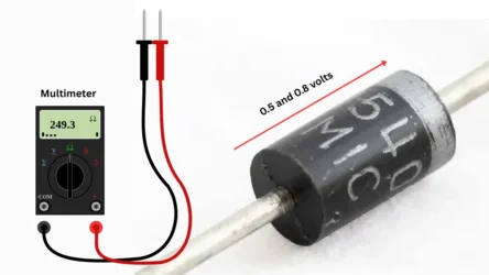
Forward voltage, also known as the forward voltage drop, is the voltage that appears across the diode when it is forward-biased. Different types of diodes have different forward voltage drops, ranging from a few tenths of a volt to a few volts. For example, standard rectifier diodes typically have a forward voltage drop of around 0.7V, while Schottky diodes have a lower forward voltage drop of around 0.2V. The forward voltage drop affects the efficiency of the diode and the amount of power it dissipates as heat.
Forward current is the current that flows through the diode when it is forward-biased. Different types of diodes have different current handling capabilities, ranging from a few milliamps to several amps. The forward current also affects the power dissipation of the diode and its maximum operating temperature.
Reverse voltage and current
Reverse voltage is the voltage applied across the diode in the reverse direction. When the reverse voltage exceeds a certain level, called the reverse breakdown voltage, the diode enters the breakdown region and begins to conduct current in the reverse direction. This can result in damage to the diode, so it’s important to choose a diode with a reverse breakdown voltage that is appropriate for the application.
Reverse current is the current that flows through the diode when it is reverse-biased. In a properly functioning diode, the reverse current should be very small, typically in the order of microamps or less. If the reverse voltage is increased, the reverse current can increase, and if it exceeds a certain level, it can result in damage to the diode.
Package type
Diode packaging refers to the physical package or housing that a diode is enclosed in. There are several different types of packages used for diodes, each with its own set of advantages and disadvantages. Some of the most common diode package types include:
- DO-41: This is a standard through-hole package that is widely used for small-signal diodes. It is cylindrical in shape and has a metal lead that extends from each end for connection to the circuit.
- SOD-123: This is a surface-mount package that is commonly used for small-signal diodes. It is a small, rectangular package that can be soldered directly onto the surface of a printed circuit board.
- Axial Lead: This is a through-hole package that is similar to the DO-41, but it has longer leads that allow for easier connection to the circuit.
- SMB: This is a surface-mount package that is commonly used for small-signal and high-frequency diodes. It is a small, rectangular package that is similar in size to the SOD-123, but it has a slightly different lead configuration.
- DO-214: This is a surface-mount package that is commonly used for high-power rectifier diodes. It is a rectangular package that is slightly larger than the SOD-123 and SMB packages, and it has a metal tab for connection to the circuit.
Transistors
Transistors are used to amplify or switch electrical signals. They come in different types, such as bipolar junction transistors (BJTs) and field-effect transistors (FETs).
Transistor types
Here is a table that summarizes the different types of transistors and their characteristics:
| Type of Transistor | Symbol | Characteristics |
|---|---|---|
| NPN Bipolar Junction Transistor (BJT) | NPN | An NPN transistor is a type of bipolar junction transistor (BJT) that has a base, collector, and emitter. When a voltage is applied to the base, it controls the flow of current between the collector and emitter. NPN transistors are commonly used in digital and analog circuits for amplification, switching, and voltage regulation. |
| PNP Bipolar Junction Transistor (BJT) | PNP | A PNP transistor is similar to an NPN transistor, but it has the polarities of the base, collector, and emitter reversed. When a voltage is applied to the base, it controls the flow of current between the emitter and collector. PNP transistors are less common than NPN transistors but are still used in a variety of applications. |
| Field Effect Transistor (FET) | N-Channel FET or P-Channel FET | Field effect transistors (FETs) are a type of transistor that uses an electric field to control the flow of current. FETs come in two main types: N-channel and P-channel. N-channel FETs have an N-type semiconductor channel, while P-channel FETs have a P-type semiconductor channel. FETs are commonly used in digital circuits for switching and voltage regulation, and in analog circuits for amplification and impedance matching. |
| Metal Oxide Semiconductor Field Effect Transistor (MOSFET) | N-Channel MOSFET or P-Channel MOSFET | Metal oxide semiconductor field effect transistors (MOSFETs) are a type of FET that uses a metal-oxide-semiconductor (MOS) structure instead of a traditional semiconductor channel. MOSFETs are available in N-channel and P-channel versions and are commonly used in digital and analog circuits for amplification, switching, and voltage regulation. MOSFETs are known for their high input impedance, fast switching speeds, and low power consumption. |
Voltage and current ratings
The voltage and current ratings of a transistor are important parameters to consider when selecting a transistor for a specific application. These parameters determine the operating range of the transistor and help to ensure that it can handle the demands of the circuit without failing.
The voltage rating of a transistor is the maximum voltage that can be applied to the collector-emitter (VCE) or drain-source (VDS) terminal without causing permanent damage to the device. This is known as the maximum collector-emitter voltage (VCEO) or drain-source voltage (VDSS). The voltage rating is an important parameter to consider in circuits where the transistor will be exposed to high voltages, such as in high-voltage switching circuits or voltage regulation circuits.
The current rating of a transistor is the maximum current that can be passed through the collector-emitter (ICE) or drain-source (IDS) terminal without causing permanent damage to the device. This is known as the maximum collector current (IC) or drain current (ID). The current rating is an important parameter to consider in circuits where the transistor will be handling high currents, such as in power amplification circuits or high-current switching circuits.
Gain and frequency response
Transistor gain and frequency response are two important parameters to consider when selecting a transistor for a specific application.
Transistor gain is a measure of the amplification provided by the transistor. It is defined as the ratio of the output signal to the input signal and is usually specified as the current gain (hFE), voltage gain (hfe), or power gain (hPA). The gain of a transistor is a key factor in determining the overall performance of an amplifier circuit and is often a major consideration in the design process. The gain of a transistor can be influenced by factors such as temperature, current, and frequency, among others.
Frequency response is a measure of the ability of a transistor to respond to signals over a range of frequencies. It is specified as the frequency range over which the transistor provides a specified level of gain. The frequency response of a transistor is a key factor in determining its suitability for high-frequency applications, such as radio frequency (RF) amplifiers, or low-frequency applications, such as audio amplifiers. The frequency response of a transistor can be influenced by factors such as the gain-bandwidth product (GBW), capacitive loading, and parasitic elements, among others.
Package type
Here is a table of some common transistor package types and their characteristics:
| Package Type | Description | Applications |
|---|---|---|
| TO-92 | Small plastic case, leads bent at 90 degrees | Small signal transistors |
| SOT-23 | Small surface-mount package | Small signal transistors for high-frequency applications |
| TO-220 | Large package with large heatsink area | Power transistors for high-power applications |
| TO-247 | Similar to TO-220 but with slightly different dimensions | High-power transistors that require a large heatsink area |
| TO-3 | Large and robust package with large heatsink area | High-power transistors |
Integrated Circuits IC
IC Consist of multiple transistors, diodes, resistors, and other components on a single piece of semiconductor material. They come in different types, such as operational amplifiers (op-amps), microcontrollers, and memory chips.
Also Know : More about Integrated Circuit or IC
IC type
| IC Type | Description |
|---|---|
| Microcontroller | A small computer on a single integrated circuit used in embedded systems |
| Operational Amplifier (Op-Amp) | A high-gain voltage amplifier used in analog circuits |
| Digital-to-Analog Converter (DAC) | Converts digital signals to analog signals |
| Analog-to-Digital Converter (ADC) | Converts analog signals to digital signals |
| Timer | Produces an output signal that changes state at a set interval |
| Voltage Regulator | Provides a stable output voltage despite changes in input voltage or load current |
| Field-Programmable Gate Array (FPGA) | A type of programmable logic device used in digital circuits |
| Memory | Stores digital data, including RAM (random-access memory) and ROM (read-only memory) |
| Transceiver | Used for transmitting and receiving data in communication systems |
| Power Amplifier | Amplifies power in analog circuits |
| Multiplexer/Demultiplexer | Used to switch signals between different channels or to combine multiple signals into one channel |
| Phase-Locked Loop (PLL) | Used for frequency synthesis, demodulation, and clock recovery in communication systems |
Pin count and package type
ICs come in a variety of package types and pin counts, depending on their function and application. Here are some common package types and their corresponding pin counts:
| Package Type | Pin Count |
|---|---|
| Dual Inline Package (DIP) | 8-40 pins |
| Small Outline Integrated Circuit (SOIC) | 8-28 pins |
| Quad Flat Package (QFP) | 32-304 pins |
| Ball Grid Array (BGA) | 4-1700+ pins |
| Pin Grid Array (PGA) | 84-1824 pins |
| Thin Small Outline Package (TSOP) | 4-100 pins |
| Plastic Leaded Chip Carrier (PLCC) | 20-84 pins |
| Ceramic Dual Inline Package (CDIP) | 8-64 pins |
| Dual Flat No-lead (DFN) | 2-12 pins |
| Quad Flat No-lead (QFN) | 8-144 pins |
Supply voltage and current
The supply voltage and current requirements of an IC (integrated circuit) can vary widely depending on the specific IC and its application. Here are some examples of typical supply voltage and current ranges for different types of ICs:
| IC Type | Supply Voltage Range | Supply Current Range |
|---|---|---|
| Microcontroller | 1.8-5V | 1-100 mA |
| Operational Amplifier (Op-Amp) | 1.8-36V | 0.1-20 mA |
| Digital-to-Analog Converter (DAC) | 2.7-5.5V | 1-10 mA |
| Analog-to-Digital Converter (ADC) | 2.7-5.5V | 1-10 mA |
| Timer | 1.5-18V | 1-10 mA |
| Voltage Regulator | 1.2-36V | 1-100 mA |
| Field-Programmable Gate Array (FPGA) | 1.2-3.3V | 1-100 mA |
| Memory | 1.8-5V | 1-100 mA |
| Transceiver | 1.8-5V | 10-100 mA |
| Power Amplifier | 1.8-36V | 10-100 mA |
| Multiplexer/Demultiplexer | 1.8-5V | 1-10 mA |
| Phase-Locked Loop (PLL) | 1.8-5V | 1-10 mA |
Inductor
An inductor is a passive electronic component that stores energy in a magnetic field when an electric current flows through it. It is essentially a coil of wire that is wound around a core made of a ferromagnetic material, such as iron, that increases the inductance of the coil.
When an electric current flows through an inductor, a magnetic field is created around the coil. The strength of the magnetic field is proportional to the amount of current flowing through the coil and the number of turns in the coil. When the current through the inductor changes, the magnetic field around the coil changes as well, which creates an electromotive force (EMF) that opposes the change in current. This phenomenon is known as inductance, and it causes inductors to resist changes in current flow.
Inductance Value
The inductance value of an inductor is a measure of its ability to store energy in a magnetic field, and it is typically measured in henries (H). The inductance value of an inductor depends on a number of factors, including the number of turns in the coil, the size and shape of the coil, and the type of core material used.
Physical size and packaging
Inductors are available in a wide range of physical sizes and packaging types to suit different applications in electronic circuits. The physical size of an inductor depends on the inductance value, the number of turns in the coil, and the size and shape of the core material used.
Small inductors, such as surface-mount inductors (SMD), are commonly used in modern electronics due to their compact size and ease of use in automated assembly processes. These inductors are available in a variety of sizes and shapes, ranging from small chip inductors to larger, cylindrical or toroidal inductors.
Through-hole inductors, which have leads that can be soldered to a circuit board, are also available in a range of sizes and shapes, from small axial-leaded inductors to larger, radial-leaded inductors.
Operating frequency range
The operating frequency range of an inductor depends on its physical construction and electrical characteristics, including the inductance value, the resistance of the wire in the coil, and the frequency-dependent effects of the core material, if any.
In general, smaller inductors with lower inductance values and thinner wire can be used at higher frequencies, while larger inductors with higher inductance values and thicker wire may be better suited for lower frequencies. The core material used in the inductor can also have an impact on the operating frequency range, as some materials may exhibit frequency-dependent losses or saturation effects.
DC resistance
The DC resistance of an inductor is the resistance of the wire in the coil, and it is typically measured in ohms. The DC resistance of an inductor is important because it affects the amount of power that is dissipated in the inductor when a current flows through it. This power dissipation can lead to heat generation and can affect the overall efficiency of the circuit.
The DC resistance of an inductor depends on a number of factors, including the wire gauge, the number of turns in the coil, and the length of the wire. In general, larger wire gauges and longer wire lengths result in higher DC resistance, while more turns in the coil can increase the inductance but also increase the DC resistance.
Relay
Relays are electrically operated switches that use an electromagnetic field to control the opening and closing of one or more sets of contacts. Relays are commonly used in electronic circuits to control the flow of power or signals between different parts of a circuit.
Relay Contact type
| Contact Type | Symbol | Description |
|---|---|---|
| Normally Open (NO) | NO | Contacts are open when the relay is not energized. |
| Normally Closed (NC) | NC | Contacts are closed when the relay is not energized. |
| Single Pole Single Throw (SPST) | SPST | One set of NO or NC contacts. |
| Single Pole Double Throw (SPDT) | SPDT | One set of NO and one set of NC contacts. |
| Double Pole Single Throw (DPST) | DPST | Two sets of NO or NC contacts. |
| Double Pole Double Throw (DPDT) | DPDT | Two sets of NO and two sets of NC contacts. |
Contact rating (voltage and current)
The voltage and current ratings of a relay contact depend on the specific relay and the application in which it is being used. In general, the contact rating specifies the maximum voltage and current that the contacts can safely switch without sustaining damage or causing a safety hazard.
The voltage rating of a relay contact is typically given in units of volts AC or DC, and it represents the maximum voltage that the contact can switch without breaking down or arcing. The current rating of a relay contact is typically given in units of amperes (A) or milliamperes (mA), and it represents the maximum current that the contact can carry without overheating or sustaining damage.
Package type
| Package Type | Description |
|---|---|
| Through-Hole | Designed to be mounted onto a printed circuit board (PCB) by inserting the leads through holes in the board and soldering them in place. |
| Surface-Mount | Designed to be mounted directly onto a PCB using surface-mount technology (SMT), which involves soldering the leads to pads on the board. |
| Panel Mount | Designed to be mounted onto a panel or chassis using screws or bolts. |
| DIN Rail Mount | Designed to be mounted onto a standard DIN rail, which is commonly used in industrial control applications. |
| Plug-In | Designed to be inserted into a socket or base, which provides a secure connection and simplifies replacement. |
| Reed | Uses a magnet and a thin metal reed to make or break electrical contacts, and is often used in low-power applications. |
| Solid-State | Uses semiconductor devices, such as transistors or thyristors, to make or break electrical contacts, and is often used in high-speed and high-reliability applications. |
In this Article i am included some common electronic components characteristic’s and their uses. This are most popular electronic components using day by day in electronic circuit designing. Before you building an electronic circuit project you must need a proper knowledge about every each and single components using in the electronic circuits.