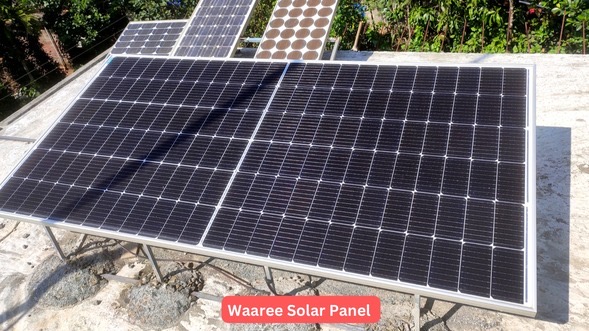
A solar tracking system is a device or a circuit that helps solar panels to move in the direction of the sun’s path, which maximizes their energy output.
There are different ways to design a solar tracking system, but a popular method involves using an electronic circuit to control the movement of the solar panel.
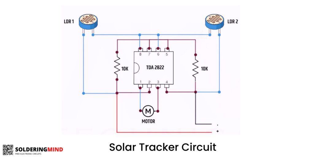
The circuit diagram for a solar tracking system is relatively simple. It uses a microcontroller or a IC circuit to control servo motors that move the solar panel in two axes – up-down and left-right.
The microcontroller receives inputs from four Light Dependent Resistors (LDRs) that detect the sunlight’s intensity in two directions.
Based on these inputs, the microcontroller calculates the optimal position for the solar panel and sends signals to the servo motors to adjust its orientation.
Solar Tracking System Circuit Diagram

How the circuit works:
First, two LDRs are placed on the east and west sides of the panel to detect the sunlight’s intensity in the left-right direction.
The IC uses the readings from the LDRs to determine the difference in sunlight intensity between the east-west and north-south directions.
Based on this difference, the the IC decides the solar panel’s optimal position to maximize sunlight exposure.
It then sends signals to the servo motors, which move the panel in the required direction to achieve the optimal position.
The movement of the servo motors is controlled by a pulse-width modulation (PWM) signal generated by the driver IC.
You may also like
📌 How to check if solar panel is charging battery
📌 Steps to Connect a solar panel to Lead acid battery


