Introduction
Did you get boared from your guitar amplifier sound? Do you want to boost the treble from the guitar amplifier. try this very easy circuit to boost the treble from the audio source.
The simple treble booster circuit is highly effective in enhancing the overall sound quality of an electric guitar, as well as other electronic equipment producing audio output. This circuit is designed to amplify high order harmonics, resulting in a more distinguished and pleasing sound.
This type of circuit produces a relatively flat response at bass and many midrange frequencies. while delivering a substantial boost to the upper midrange and lower treble frequencies.
It is common to apply a moderate emphasis on the upper treble to achieve a balanced and low-noise output, preventing the sound from becoming overly harsh.
What is a Treble Booster Circuit?
The treble sound means the high-frequency tone from the audio signal. The frequency range of the treble is in between 6Khz to 20Khz. The human can hear this sound as a treble. The treble booster circuit is very helpful for the guitarist to boost their high end of the tonal spectrum. So this circuit is the perfect one to boost the additional treble from the input audio signals.
Frequency Response of Treble Booster Circuit
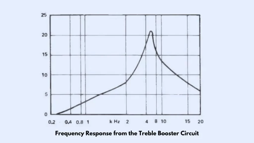
The frequency response of the treble booster circuit is given in the graph. This visual representation showcases how the circuit enhances specific frequency ranges, contributing to an improved audio output especially the Treble.
Treble Booster Circuit is Good for Music?
Definitely Yes, The treble booster circuit only boosts the targeted audio frequency range. The treble boosting will create bright and core comfortable airy sounds.
Circuit Diagram
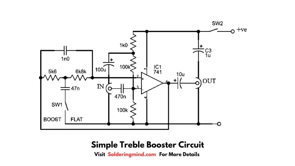
Components Required
| Component | Value | Quantity |
|---|---|---|
| IC | UA741 op amp | 1 |
| Resistor | 5k6, 6k8,100k, 1k | 1, 1, 2, 1 |
| Capacitor | 1uf, 10uf, inf, 470nf, 100uf, 47nf | 1, 1, 1, 1, 1 |
| Switch | – | 2 |
| Battery | 9-12V DC | 1 |
Working
The treble booster circuit is working based on an op-amp IC. This IC circuit is in noninverting amplifier mode. The resistors R4 and R5 is biased by the noninverting input of the op amp. The capacitors C4 and C5 block at the input and output section.
When Switch 1 is open a 100% negative feedback is happening via R1, R2, and C1. This will make a unity gain in the op amp.
While the switch 1 is pressed the C2 (47nf) capacitor gets connected, which decouple the feedback through the R1 and R2. The Feedback Via the C1 capacitor at high treble frequency makes it drop away over around 5.5Khz, and it will prevent the high frequency harmonic getting over emphasized.
You will Also Like This
- Op Amp Unity Gain
- How to Fix Grinding Noise Coming from Laptop
- Precision Rectifier using Op Amp Circuit and Working
- LM358 microphone amplifier circuit
- Delay Lamp On/Off Circuit Using Zener Diode