Let’s look at what a precision rectifier is, The Precision rectifier input voltage will be the same as the output voltage, and there is no voltage drop across the diode this type of rectifier circuit is known as a precision rectifier then how it is different from the normal rectifier and its works.

Before knowing about precision rectifiers, First, you need to know what is a normal rectifier and how it is working. Also, you can get an idea about how to build a precision rectifier circuit using op-amp.
Rectifiers
The rectifier is also known as a diode it can rectify the input voltage. Most electronic circuits are built with rectifiers. Rectifiers are of different types, so I am not going deep through these types. You need to know what is a rectifier and how it works that’s it.
Working of normal rectifier
The rectifier circuit is in half wave and also full wave rectifier. From the name itself, clear that half-wave rectification and also full-wave rectification. When an AC source is connecting to the single diode. Now the diode circuit can only rectify the Positive side of the AC pulse. ( The AC pulse is in a wave from one positive peak and another negative peak ).
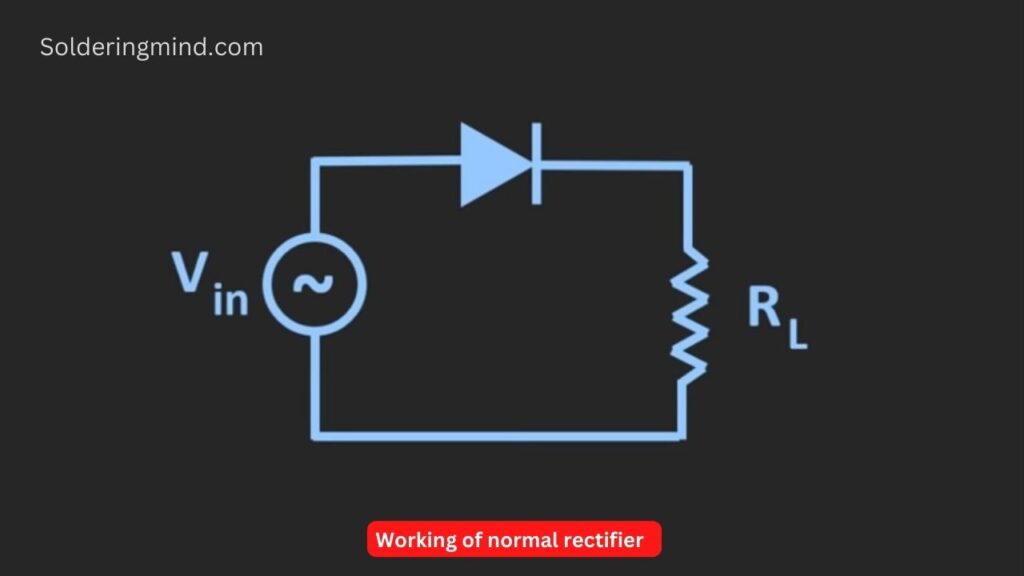
In that time only half a portion of the input voltage is getting through the rectifiers known as half-wave rectifiers the other side AC signal gets the loss. To avoid this problem full-wave rectifiers are used. The full wave rectifier is built with Two diodes or four diodes ( Bridge rectifier ) which can able to rectify both sides of the AC pulse. Now it is clear about the half-wave and Full-wave bridge rectifiers.
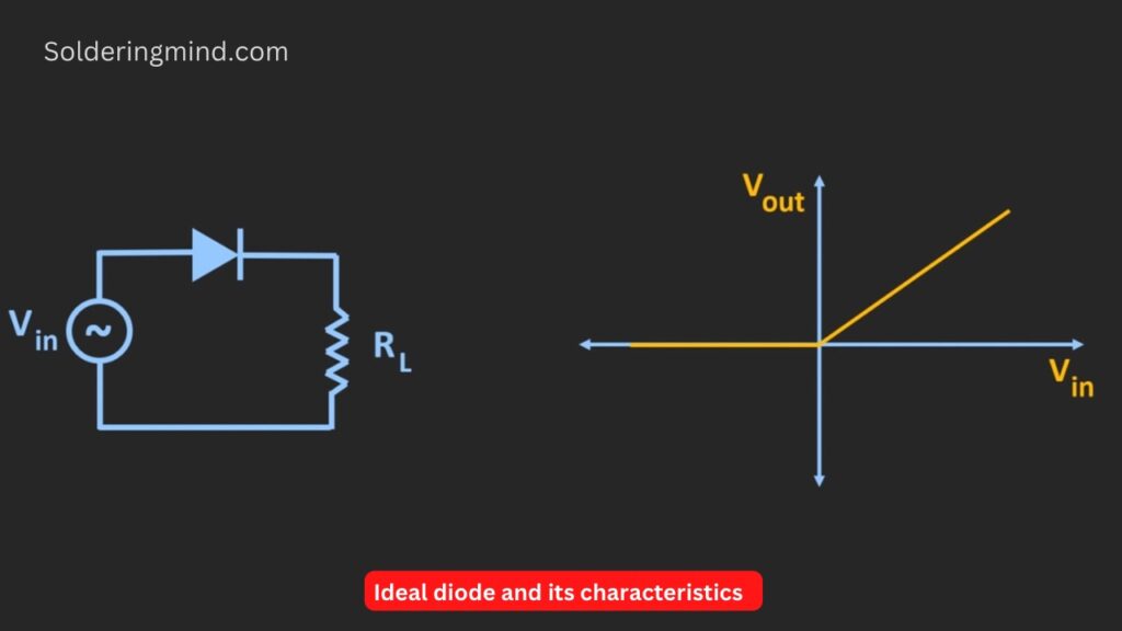
What are ideal diodes?
The ideal diode is different from the normal diode function. If a sine wave is applied through these diodes the output will be the same voltage as the input half wave of the signal. There is no initial voltage drop or loss in the output. The chart shows that the linear line when the input is negative at the time the output is zero. Whenever the input voltage is positive at the time the output will follow the input signal. So these are known as ideal diodes.
But in a normal rectifier circuit, the diode will conduct only when the applied input signal is more than the forward voltage drops across the diodes. The actual peak waveform is smaller than the ideal diodes ( small loss of energy in normal diodes ).
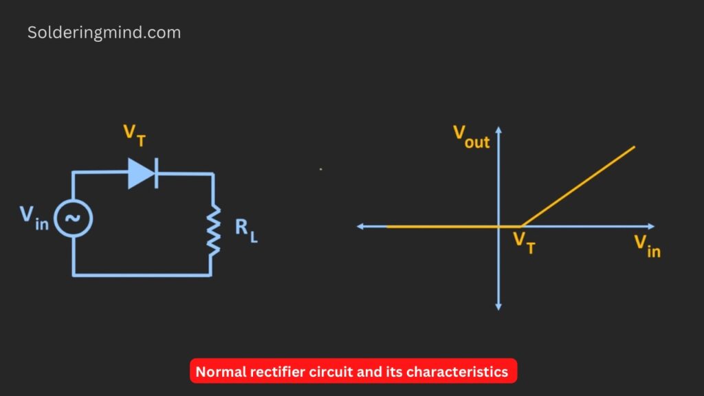
If you check the given graph of the normal rectifier the same input AC pulse is applied to the rectifier when the input voltage is zero the output will be zero. But the diode will only conduct when the applied input voltage is more than this threshold voltage. Now this voltage drop across the diode will not be much problem in AC to DC conversion. But whenever the rectifier circuit is used for small signal processing and signal conditioning then it will not work.
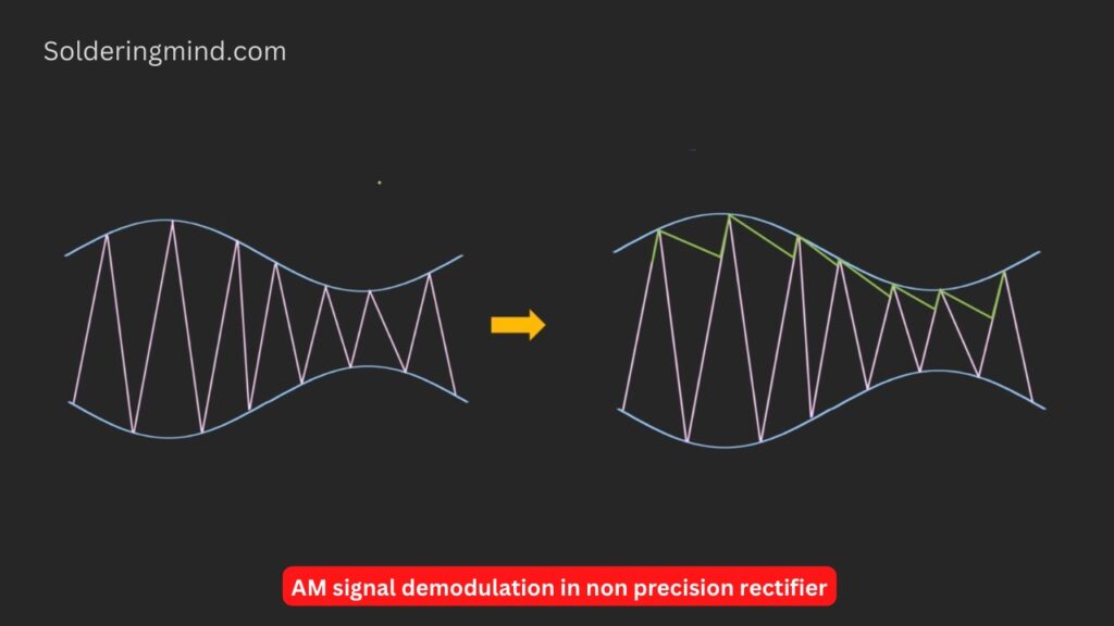
Example: The input voltage applied to the rectifier is smaller than the diode forward voltage drop. In this case, the rectifier circuit is not able to conduct the input voltage. If the input signal is AM signal, the input voltage signal voltage is much smaller than the diode’s voltage drop. Sometimes we need to demodulate the AM signals then this is not possible because of the diode’s forward voltage drop.
So in such a specific case, the precision circuit using op-amp is very helpful. The given figure of the circuit is a simple circuit of op-amp-based precision diode schematics. It contains an op-amp IC, a Normal diode and a resistor of any value.
Precision rectifier
From this circuit, the diode acts as an ideal diode with the help of an op-amp IC. So the rectifier circuit will behave like the ideal rectifier circuit. So this circuit is also known as the super diode circuit.
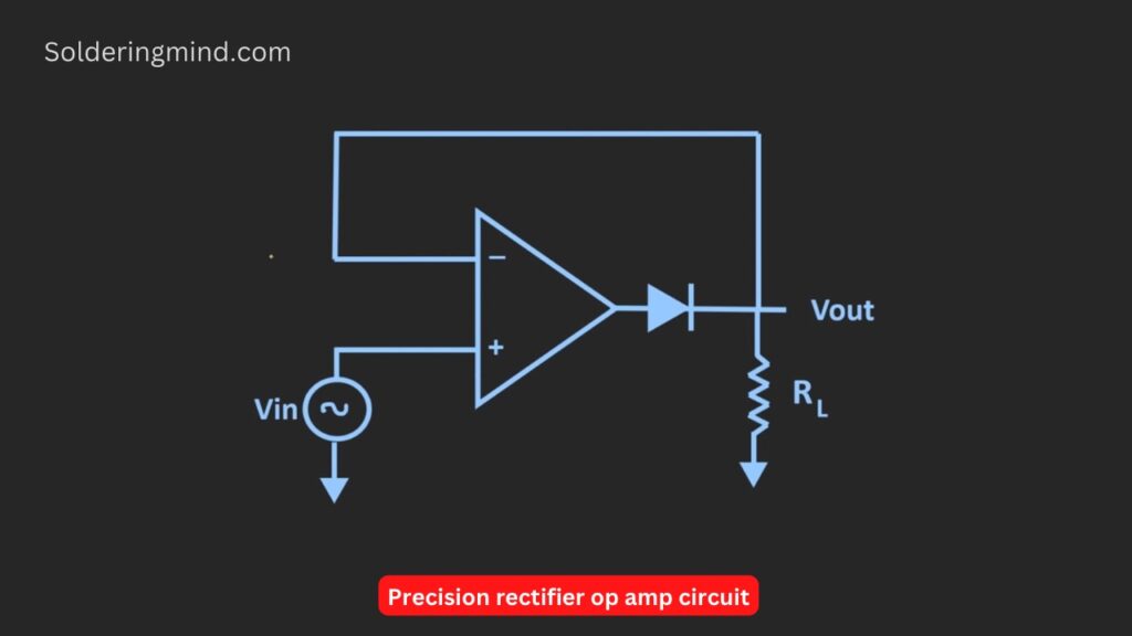
Lets we check the transfer characteristics of this precision rectifier then it will look like the ideal diodes chart. There is no voltage drop across the diode is theirs. Let’s understand how this super diode circuit works.
Working of precision rectifier
When the applied input is positive that means Vin > 0 The diode will act like a closed switch. Whenever the input voltage is applied through the circuit the same voltage will get in output through the op-amp.
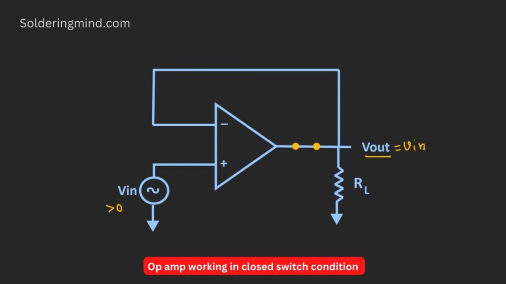
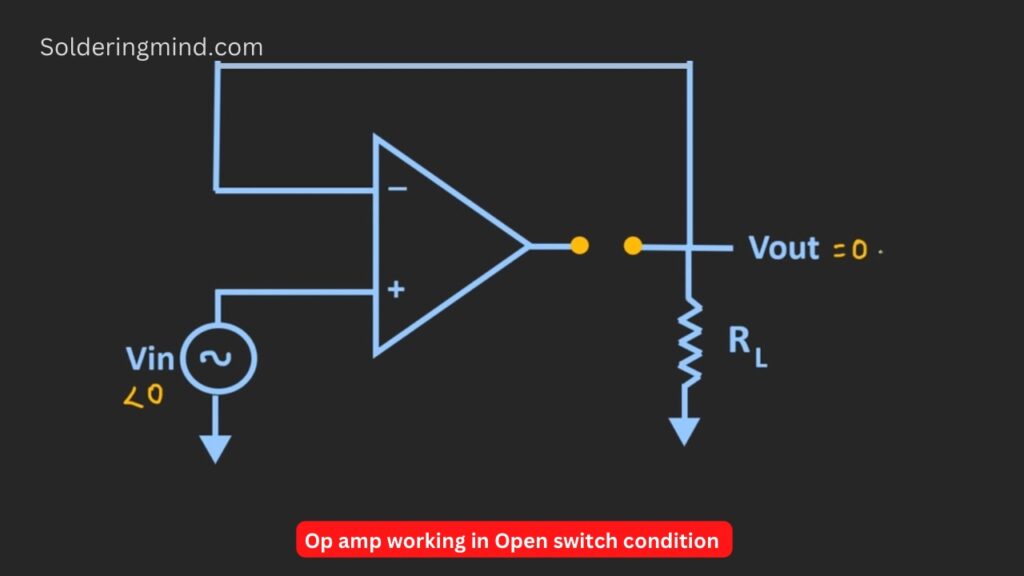
That means Vout = Vin another vice the input voltage is zero then acts like reverse bias and the switch will act as an open type given in the schematics below. Now it is clear about the working of the op-amp.
Lets we connect the diode instead of the switch mentioned in the above statement. The diode will act as an ideal diode because the diode is connected in the feedback loop. Now here we assume that
Precision rectifier Formula
VF’ = Vf/Aol
Vf’ = effective voltage drop across the diode
Vf = voltage drop across the normal diode
Aol = Open loop gain of the op-amp
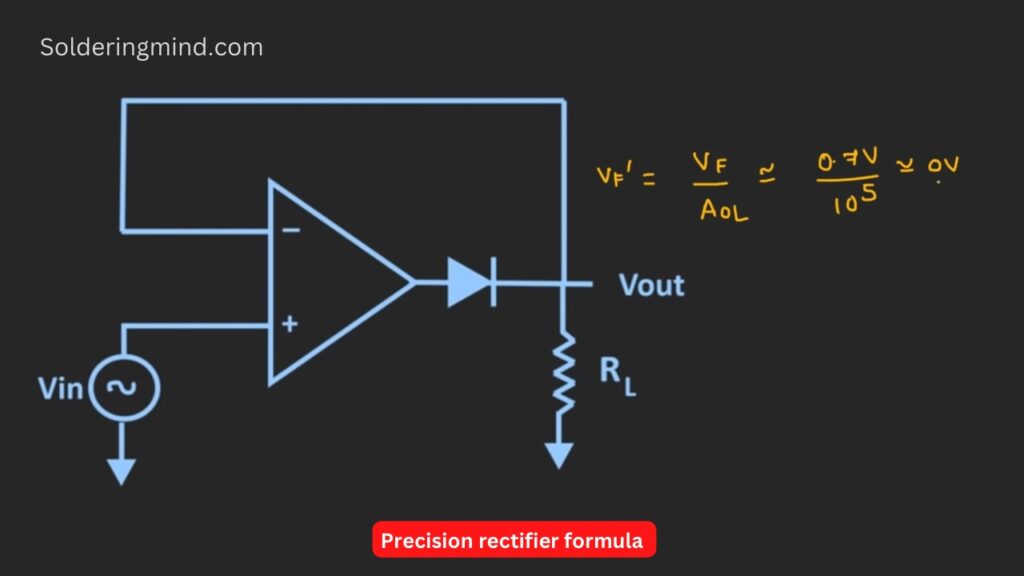
Example: voltage drop across the diode is 0.7v. So the equation become,
VF’ = 0.7/10,00000
So the effective voltage drop will be approximately zero. In the closed loop configuration, the effective forward voltage drop across the diode is equal to zero voltage, which means the diode acts like the ideal diode.
We assume that the output of the op-amp is vo’. When the diode is conducting there will be a voltage drop across the diode is about 0.7v. Here we assume that the silicon diode is used in this rectifier circuit. The the
Vout = vo’ – 0.7
Ie, vo’ = vo + 0.7v
Observing the circuit the diode is conducting one side of the diode is connected to the non-inverting input of the op-amp. So the op-amp is operating at the negative feedback configuration. We know that in the negative feedback configuration, we can apply the concept of either virtual ground or virtual short.
Even if the diode is connected in the feedback path then also it is possible to apply the concept of virtual ground or virtual short. Now for the op-amp, we know that the output voltage vo can be given as the open loop gain,
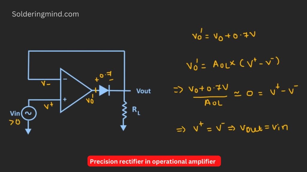
Vo’ = Aol * (+V – -V)
vo+0.7v /Aol = 0 = V+ and V- is also zero.
We can observe that whatever applied signal in the inverting input will same will get in the non-inverting input.
V+ is equal to V-
Vout = Vin
Conclusion
So you know how the precision rectifier is working. Any positive voltage above zero volts in the non inverting pin of op-amp the same voltage will get at the output so there is no voltage drop across the diode is occurs. So the total circuit acts like a precision rectifier.


Tks!…
You are welcome my friend i hope this post is very easy to understand.