Enter the Input resistance value of R1 and feedback resistor value R2 in the field to get the op-amp gain of inverting and non-inverting op-amp configuration.
Inverting Op Amp Gain Calculator
Non-Inverting Op Amp Gain Calculator
Non-Inverting Op-Amp Gain Calculator
What is inverting op-amp?
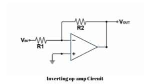
The inverting op-amp setup is a basic electronic circuit that uses most electronic systems. The circuit consists of two resistors, R1 and R2. This configuration performs signal amplification while inverting the phase of the input signal.
- The input signal is connected to the negative terminal of the op-amp using a resistor R1
- The resistor (feedback resistor) is connected between the op-amp output and negative input.
- The positive terminal of the op-amp is connected to the ground connection.
Inverting op-amp Gain Formula
This circuit diagram represents the inverting op-amp circuit using an operational amplifier and resistors R1 and R2. The formula for the gain in an inverting op-amp configuration is calculated by using the formula of,
Gain = R2/R1.
What is a Non inverting op-amp?
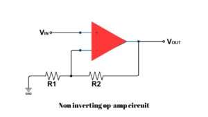
The non-inverting op-amp is another configuration using an operational amplifier. In this configuration, the input signal does not invert its phase.
- The non-inverting operational amplifier circuit includes an op-amp and two resistors.
- The input signal is connected to the non-inverting terminal of the op-amp (+)
- The resistor R1 is connected between the non-inverting input and the op-amp output.
- R2 is connected to the non-inverting (-)input and ground.
Non-Inverting op-amp Gain Formula
Gain = 1+R2/R1