The Motion sensor circuit is working based on a 555 timer IC. The entire article contains PCB layout of Motion sensor automatically activating light PCB. The circuit can handle the 220v AC supply.
220v AC Motion Sensor project PCB Layout
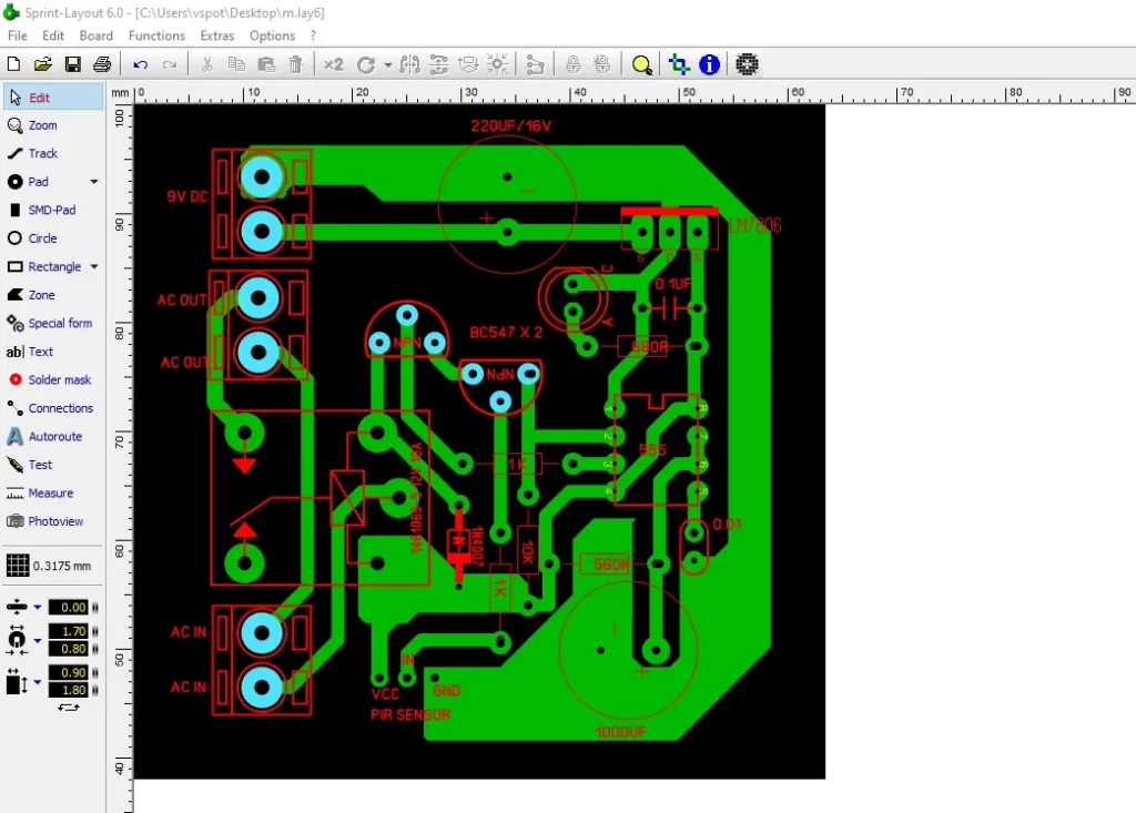
Working
The Circuit is working based on a 555 IC. The PIR sensor attached with the circuit board will detect the motion of human body. Then sending the data to the nearest BC547 transistor. The transistor passes the signal to pin number 2 of the 555 IC.
In that time the IC trigger the relay transistor and turn on the relay connected 220 V AC lights or Camera. This is the the basic working of this circuit. If you want to know more about it please comment your questions in the comment section.
Download PCB Layout
FAQ
The required Minimum voltage of 4.5 to 16v DC at maximum level.
Low level output voltage is 2.5v and high level output voltage is voltage 12.5v Dc.
The Passive infrared motion sensor (PIR) Will automatically do the task of turning on/off the electrical appliances or lights if any human body detected around the sensor area.


Good progress interested in the projects
Circuit PDF
Please 🙏
You can download from the given link in the post