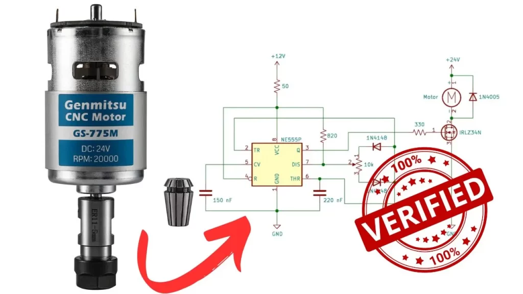
The CNC Machine needs the proper movement and speed adjustment system to work perfectly. So in this article you will get the circuit diagram and PCB layout of CNC Spindle Motor Speed Controller Circuit.
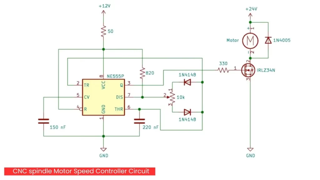
24V CNC Spindle Motor Speed Controller Circuit Diagram
Components Required
| Component | Quantity |
| 555 IC | 1 |
| IRFLZ34 or IRFZ44 Mosfet | 1 |
| 1N4141 diode | 2 |
| 150nf, 220nf capacitor | 1 |
| 1N4005 or 1N4007 diode | 1 |
| 10 k Pot | 1 |
| 50 ohms and 820ohms resistor | 1 |
Working
The Entire circuit is working based on a 555 timer IC it can efficiently control the speed of a 24V router spindle motor. The speed controlling at 500hz frequency for smooth turning of the motor shaft.
The opposite direction of the connected diode will set the trip resistance for the charge discharge of the potentiometer to same. Which fixes the frequency unchanged.
R forward + R backward = Constant duty cycle
The mosfet will turn on and off the motor at the specific frequency range and control the speed of it. The 1N4005 or 1N4007 connected parallel to the motor to protect the mosfet from back emf produced by the spindle motor.


Thks…
you are welcome